


IN THE GARAGE.
Page 31
If you've noticed an error in this article please click here to report it so we can fix it.
Some Hints on Repairs and Maintenance by Our Driver and Mechanic Readers.
THE purchase of a stand for holding engines during the process of repair is somewhat expensive, and in certain cases the cost is prohibitive when the occasions for the use of such a device are infrequent.
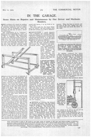
The construction of a " turnover " engine stand is described by " G.B.," of Congleton, for which this week's prize of 15s. is awerded. The horizontal members are composed of four pieces of angle iron, two of the same length, say 3 ft. 6 ins., the other pair being about 3 ft. long ; two form the outer fixed, and two the inner rotatable, members. In the first case the two sections which will be on the inside are drilled and slotted on one web each at intervals of 3 ius, in order to accommodate the engine bearer arms. The pivot pins are, of course, in the centre, for which holes of in. diameter are drilled in each member, and one at each end of 7-16-in. diameter, into which the locking bolts are inserted to keep the inside members rigidly held to the outer ones when an engine is in place. The other two portions of angle iron are now taken and three holes drilled in each, these being of suitable diameters to correspond in size and position with those made in the movable members.
Four legs are necessary, and these are made up from angle iron of 2 ft. or 2 ft. 6 ins. length, according to the height of the mechanic. About in. from the top of each leg a hole is drilled, also similar holes to correspond in the ends of the outer horizontal members. Further to strengthen the device the legs arc brazed to the fixed side members. Tie-bars between the legs are made of 1-in, by fin. iron, 1 ft. 6 ins. long, drilled with 5-16-in, holes every 2 ins, in order to provide an adjustment to compensate for the width of different engines. Diagonal tie-pieces, 1 in. by in. by 10 ins., are used to couple the legs to the tie-bars. To provide extra longitudinal rigidity, bars should be fixed parallel to the hori zontal side "pieces, 1 in. by 5-16 in. by 3 ft. 6 ins.
The pivot bolts for the inner frame are in. B.S.F.; the four locking bolts at the four corners are 746 in. diameter.
SUBSTITUTING a sound magneto for a defective one without difficulty forms the subject of a contribution from " H.W.O.," of Birkenhead. Provided the replacement instrument is of the same pattern as the one to be removed, there should be no apparent difficulty.
The first step is to set the ignition control in the fully retarded position and remove the distributor and makeand-break covers. The crankshaft is next rotated by hand until the distributor brush points to the firing position of No. 1 cylinder. The make-and-break contacts are observed
and the engine turned slowly until they are about to open.
,The holding-down strap is slacked off and the magneto removed. The replacement instrument is put in position, the setting being exactly similar to that of the one taken off. The distributor and contact-breaker cover will be interchangeable if the replacement instrument is of exactly the same type, and, therefore, the wires need not be touched. The cam ring on the make-and-break should not be changed from one magneto to another, as there is frequently a slight variation in adjustment. After the engine has been run to test the correctness of the setting, the distributor and make-and-break covers belonging to the new magneto may be fitted in place of the old ones actually in position on the new magneto.
A METHOD of reducing the internal
diameter of bushes, nuts and collars forms the subject of the contribution of " W.O.," of Nelson. The sketch intiktrates the idea, which is the use of the old principle of heating and cooling by water to shrink the metal. The part to be reduced is heated to a blood-red colour. A flat-bottomed basin containing water is previously prepared, filled to a depth slightly less than the difference between the internal and exterml diameters of the Part to be
treated. When the heat is correct, roll the part in the tray, taking care that the water does not reach the inside of the bore.
In garages employed for steam vehicles, the process of getting up steam is often accompanied by disagreeable clouds of smoke. These can easily be obviated If each of the vehicle stands has over it a.smoke extractor, which can be dropped over the chimney of the vehicle, and by which the smoke can be conveyed to the outside of the garage.
Such a fitment was made by " H.A.B.," of Itotherhatn, from
sheet-iron at a cost of approximately 15s. The lower part of the extractor is bell-shaped and allowed to fit loosely over the chimney. It can slide on an extension pipe and is supported by a balance-weight fastened to a wire connected to the bell and passing over pulleys mounted on a bracket.
The movement thus permitted allows the vehicle to be driven on and off its stand without fouling the bell.
As shown in the illustration, the extension pipe protrudes through the roof of the garage, but it is quite a simple matter to bring it out at the front or side.