


To Relieve Injection-pump Plungers of Side Loading
Page 40
If you've noticed an error in this article please click here to report it so we can fix it.
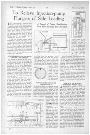
A Resume'. of Patent Specifications That Have Recently Been Published
TIIE conventional injection-pump plunger usually has on one side a -triangular recess which functions as a control edge; this, being subject to fuel pressure, creates a heavy one-sided force which tends to cause uneven wear. To avoid this is the object of an improved plunger shown in patent No. 550,050 by C,A.V., Ltd., W. E. W. Nicolls and F. M. Evans, all of Warple Way, London, W'.3.
In this case the main control edge is formed by a narrow helical groove (1) occupying about half the total circumference, whilst there is an additional groove (2) starting at the lower end of the helical groove and extending around the opposite side for about half the circle. The effect is , to create an opposing pressure which balances that of the control groove and so frees the plunger from Sict loads.
. GEAR-LEVER-OPERATED SERVO CONTROL FOR CLUTCH
TO reduce the action of gear changing to movements demanding the bare minimum of skill is the 'object of a scheme described in patent No. 549,993 by S. S. Cuy, Sauchieleigh, Albrighton, and W. E. Bullock, Saintsbury, Pattingham Road Perton, Wolverhampton. The idea is to employ a servo-cylinder coupled to the clutch arm, powered by hydraulic or pneumatic means and brought into operation by the initial movement of the gear lever.
To enable the actual gears to be shifted without skill, effort or noise it is specified that a free wheel or a second clutch " may " be provided behind the gearbox so -that the latter is momentarily disconncted from the propeller shaft, as well as the power unit, during the change. In such case, a second clutch would be actuated by -an arm (5) linked to the lever of the normal clutch.
A layout embodying the invention is depicted, in which 2 is the servo-cylinder, 3 the clutch arm and 1 a finger
projecting from the gearbox, which transmits from the lever the motion required to open the servo valve (4).
We suggest that a device for the total isolation of the gearbox would not be a preferred, but a necessary adjunct, because efforts to synchronize the gearwheels before engagement could not he made by the driver with the clutch disengaged for .the whole period of the gear-changing operation.
TO FACILITATE CONTAINER TRANSFERENCE
A''proVement to a scheme for the quick transhipment of demountable containers from road vehicles to rail trucks, and -vice versa, forms the subject of patent No. 549,534, from the National Fitch Corporation,. 420, Lexington Avenue, New York, U.S.A. The system employs side-hauling means,
comprising t w o power-driven con 5 49.534 veyor chains to pull or push the contallper on or off the truck or lorry platform.
Detailed in patent No. 544,436, the original scheme NS LAS summarized in our issue dated _Time 5, 1942. The latest specification deals mainly with two " articulated bridge pieces, which connect the sides of the two platforms and form a track for the container. Each is made in two main parts—a slidable member (3) and a swinging link (2). They are • pulled putwards—to bring them into use—from hous ' ings (1) in the lony. frame (4), and pinned to •hinged brackets (6) on . the rail truck '(5).
Slots (7) in these brackets allow some freedom of movement and permit the locking devices of the sliding member (3) to register with one of a series of recesges (10) in its vertical faces. Each locking device comprises essentially a ball (8) and a cam (9) actuated by a handle (12). When the lorry is running, the ball (8) fits into recess 11 so that no part of the attachment p?ojects.
It'is, pointed out that the combination of swinging and sliding movement, afforded by the bridge pieces, is particularly advantageous when the two vehicles cannot be exactly aligned, in respect of parallelism or. their relative levels.
NEW WAY OF MAKING HARDENED PISTON RINGS
AMETHOD Of producing, hardened and tempered piston rings is shown in patent No. 550,322 from R., C. Cross and the Crois Manufacturing Co. (1938), Ltd., 39, Midford Road, Combe Down, Bath. The scheme described is a means for gapping the rings which are produced in a manner covered by an earlier patent, namely, by winding. red-hot strip on to a cold mandrel, the chilling effect of which hardens the. metal, and then cutting tilt coil into rings which are afterwards trued from helical to flat form.
The next step, detailed in the present specification, is to spring the rings out to the ' required oversize diameter, and this is performed in the mannerillustrated:. A mandrel is provided with a longitudinal strip (1) of a width equal td the-required gap. A large number of rings (2) are threaded on, and secured by damping at each end. This assembly,is then immersed in a molten-lead bath which not only tempers the rings to the :desired degree of hardness, but also imparts a permanent set to them in the sprung-open position.