


An Experimental Independent Suspension Scheme
Page 47
If you've noticed an error in this article please click here to report it so we can fix it.
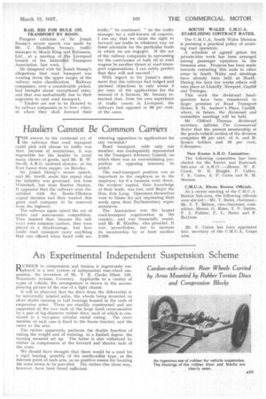
RU.BBER in compression and torsion is ingeniously employed in a new system of independent rear-wheel suspension, the invention of Mr. T. E. Clarke •Hirst, 129, Warubody Avenue, Coventry. Applicable to a variety of types of vehicle, the arrangement is shown in the accompanying picture of the rear of a light chassis.
It will be observed that the drive from the differential is by universally jointed axles, the wheels being mounted on short shafts running in ball bearings housed in the ends of suspension arms. These are sturdily constructed and are supported at the two ends of the large fixed cross-member by a pair of big-diameter rubber discs, each of. which is contained in a two-piece circular metal casing. The inner member of each case is fixed to the frame bracket, and the outer to the arm.
The rubber apparently performs the double function of taking the weight and of resisting, to a limited degree, the turning .moment set up. The latter is also withstood by rubber in compression at the forward and shorter ends of the arms.
We should have thought that there would be a need for a rigid bearing, possibly of the needle-roller type, at the fulcrum point, of each arm, as no positive means for locating the arms seems to be provided. The rubber disc alone may, however, have been found sufficient.