


FODEN SIX-WHEELER
Page 80
If you've noticed an error in this article please click here to report it so we can fix it.
A Resume of Recently Published Patent Specifications.
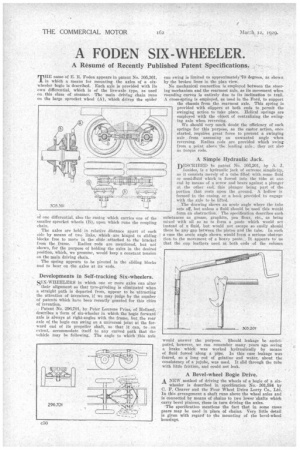
TiiE name of E. It. Foden appears in patent No. 305,361, in which a means for mounting the axles of a sixwheeler bogie is described. Each axle is provided with its own differential, which is of the live-axle type, as used on this class of steamer. The main driving chain runs on the large sprocket wheel (A), which drives the spider
of one differential, also the casing which carries one of the smaller sprocket wheels (B), upon 'which runs the coupling chain.
The axles are held in relative distance apart at each side by means of two links; which are hinged to slidingblocks free to move in the slide attached to the* bracket from tbe frame. Radius rods are mentioned, but not shown, for the purpose of holding the axles in the desired Position, which, we presume, would keep a constant tension on the main driving chain.
The spring appears to be pivoted in the sliding blocks and to bear on the axles at its 'ends.
Developments in Self-tracking Six-wheelers.
SIX-WHEELERS in which one Or more axles can alter their alignment so that tyre-grinding is eliminated when a straight path is departed from, appear to be attracting the attention of inventors, if we may judge by the number of patents which have been recently granted for this class of invention.
• Patent No. 296,701, by Peter Lourens Prins, of Holland, describes a form of six-wheeler in which the bogie forward axle is always at right-angles with the frame, but the rear axle of the bogie can swing on a universal joint at the kirward end of its propeller shaft, so that it can, to .an extent, accommodate itself to any curved path that the vehicle may be following. The angle to which this axle can swing is limited to approximately /0 degrees, as shown by the broken lines in the plan view: No mechanical connection is employed between the steering mechanism and the rearmost axle, as its movement when rounding curves is entirely due to its inclination to trail. A cross-spring is employed, as used in the Ford, to support the chassis from the rearmost axle. This spring is provided with slippers at both ends to permit the swinging action to take place. Helical springs are employed with the object of centralizing the swinging axle when reversing.
We should very much doubt the efficiency of such springs for this purpose, as the castor action, once started, requires great • force to prevent a swinging axle from assuming an unwanted angle when reversing. Radius rods are provided which swing from, a point above 'the leading axle; they act also as torque rods.
A Simple Hydraulic Jack.
DESCRIBED tin patent No. 303,201, by A. J. • lonides, is a hydraulic jack of extreme simplicity, as it consists merely of a tube filled with some fluid or semi-fluid which is forced into the tube at one end by means of a Screw and bears against a plunger at the other end, this plunger being part of the portion that rests upon the ground. A hollow is formed in the casing, or a hook provided to engage with the axle to be lifted.
The drawing shows an acute angle where the tube sets off, but unless a fluid should be used this would form an obstruction. Thespecification describes such substances as grease, graphite, pea flour, etc., as being mixed with oil so as to form a paste which would act instead of a fluid, but would not escape so easily should there be any gap between the piston and the tube. In such a case the acute angle shown would form a serious obstruction to the movement of a heavy Paste. , It appears to us that the cup leathers used at both ends of the column
would answer the purpose. should leakage be anticipatitd, however, we can remember many years ago seeing a brake which was worked hydraulically by means of fluid forced along a pipe. In this case leakage was feared, so a long rod of gelatine and water, about the consistency of a jujube, was used. It slid through the tube with little friction, and could not leak.
A Bevel-wheel Bogie Drive. A NEW method of driving the wheels of a bogie of a six
wheeler is described in specification No. 301,584 by C. F. Cleaver and the Four Wheel Drive Lorry Co., Ltd. In this arrangement a shaft runs above the wheel axles and is connected by means of chains to two lower shafts which carry bevel pinions, these in turn driving the axles.
The specification mentions the fact that in some cases gears may be used in place of chains. Very little detail is given with regard to the mounting of the bevel-wheel housings.