


Patents Completed.
Page 26
If you've noticed an error in this article please click here to report it so we can fix it.
Air Compression Simplified. A Unique Sleeve-valve Engine.
H. W. WALKER, No. 24,173, dated 21st May, 1913.—This pump is a separate fitting which can be attached to the cylinder of an internal-combustion engine, for example by screwing it into the opening for the sparking plug.
It comprises a cylinder of two diameters having a compound piston freely reciprocating in it. The free end of the larger part of the cylinder is in direct communication with the combustion chamber of the engine, and the top end of the smaller cylinder is provided with non-return valves for the inlet and delivery of the fluid which is being compressed. On the inlet stroke of the engine, the pump-piston is drawn down by the suction on the under side of it, and air is drawn in through the non-return valve.
On the engine compression stroke, the increased pressure forces the pump-plunger up again, thereby compressing and delivering the air through the delivery valve.
R. REID, NO. 16,241, dated 15th July, 1913.—This specification describes a sectional solid or cushion tire in which the rubber tread is formed of a series of blocks, each vulcanized on to a separate segment of a metal band. The latter are provided with teeth or grooves in the usual manner, to get a good grip of the rubber. The rubber blocks are recessed at each end so as to form grooves, and these are preferably inclined across the tire.
The metal segments are assembled on a continuous band forming the rim of the wheel and are held in place by side flanges secured by bolts passing through the felloe.
Creeping of this tire is prevented either by keying Some of the segments to the rim or by providing a T-headed bolt passing through the rim and having the cross part of the T lying between two of the blocks.
The specification also describes twin tires made in accordance with this invention, and in this case the grooves between the blocks are preferably inclined in opposite directions.
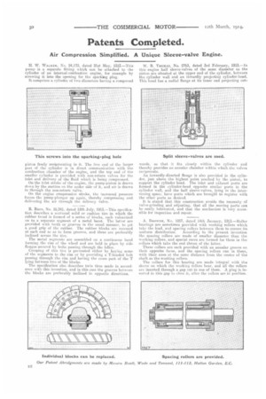
W. R THOMAS, No. 2763, dated 3rd February, 1913.—In this engine half sleeve-valves of the same diameter as the piston are situated at the upper end of the cylinder, between tho cylinder wall and an inwardly projecting cylinder-head. Thia head has a radial flange at its inner end projecting out
wards, so that it fits closely within the cylinder and thereby provides an annular chamber within which the valves reci prorate. An inwardly-directed flange is also provided in the cylinder, just above the highest point reached by the piston, to support the cylinder head. The inlet and exhaust ports are formed in the cylinder-head opposite similar ports in the cylinder wall, and the half sleeve-valves, lying in the intervening space, have ports which are brought to register with the other ports as desired.
It is stated that this construction avoids the necessity of valve-grinding and adjusting, that all the moving parts can he easily lubricated, and that the mechanism ia very accessible for inspection and repair.
A. BROWNE, No. 1057, dated 14th January, 1913.—Roller bearings are sometimes provided with working rollers which take the load, and spacing rollers between them to ensure its
uniform distribution. According to the present invention the spacing rollers are made of smaller diameter than the working rollers, and special races are formed for them in tho collars which take the end thrust of the latter.
These collars are each provided with an annular groove on their opposite faces, and the spacing rollers run in these, with their axes at the same distance from the centre of the shaft as the working rollers.
The collars for this hearing are made integral with tho sleeve on which the working rollers bear, and all the rollers are inserted through a gap cut in one of them. A plug is inserted in this gap to close it, after the rollers are in position.