


Korn Drivers &Mechan ic s
Page 24
Page 25
If you've noticed an error in this article please click here to report it so we can fix it.
TEN SHILLINGS WEEKLY is paid for the best communication received, and One penny a line of ten words for anything else published, with an allowance for photographs.
Send as an account of any special incident of your work or experience, Ifsvilable, we will edit your notes, suPPly a sketch when required, and pay you for everything published, Mention your employer's name, in Confidence, as evidence of good faith. Address to Tire Editor, THE COMMERCIAL MOTOR, Rosebery Avenue, London, E.G.
Light Up Your Lamps At
6.56, Thursday ; 0.58, Friday ; 7.0, Saturday ; 7.3, Monday; 7.5, Tuesday ; 7.6, Wednesday.
A Measuring Tool Useful for Turners.
[1456] " V.W.C." (Camberwell) writes:—'' I enclose a sketch [We have had this redrawn—ED,] and a Liescription of a tool which may prove useful to some
of the mechanic readers of your 'D. and M.' pages. I made it in the first instance to overcome the difficulty of measuring jobs in the lathe, particularly those in winch comparatively large radii occur " The tool consists of a 12 in, steel rule fitted with a special sliding square, which can be locked at any point along the rule. The square was made from some pieces of sheet steel, one piece was slightly thicker than the rule, to form a distance piece for it, and the other pieces were 16 S.W.G. and 10 S.W.G. respectively. The 16 S.W.G. piece I cut to form the blade, making it 4 ins, long by 21, ins. wide. The distance piece I carefully filed true to slide on the rule.
"I then fixed the square together by means of three
in. rivets, using the 10 S.1147.G. steel as a backing piece, afterwards sliding the square on the rule and truing it up. To enable the instrument to be fixed in any required position I drilled and tapped a. hole in the backing piece, and fitted into it a fine-threaded milled-head screw, and by screwing it up the rule is tightly gripped.
"In order to allow for quick and accurate adjustment I found it advisable to bevel down the front of the square.
Twist Drills and How to Grind Them.
The sender of the following communication has been awarded the 103. prise this week.
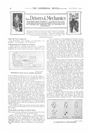
[14W7] " S.C." (Glasgow) writes :—" May I add a few remarks to H.B.'s ' contribution (letter No. 1429) respecting the faultygrinding of twist drills, also a suggestion for an improvement on drill grinding as generally carried out. I enclose a sketch [We have had this redrawn.—En.] to illustrate my reasoning, E2
"Your contributor well emphasizes the evils attending the use of a twist drill with the profile angle of the cutting edges, relative to the axis, different for each flank of the drill, or with one flank of the drill ground away more than the other, which leaves the point eccentric. . He clearly shows how such a drill will tend to bore a hole larger than itself in diameter. He does not speak, however, of the effects of using a drill with the. cutting edges themselves at different angles, that is, with more ' backing off ' from the cutting edge on one flank than on the other. The consequences of using a tool so ground are such that the work piece is more amenable to cutting by one edge than the other, and the point of the drill is forced out of centre.
"I would point out that the inclined angle of a drill nose should be 120 degrees, or rather less, for steel, and from 90 degrees to 100 degrees for cast-iron, the angle for such metals as brass and copper being somewhere between. For thin plate work the angle should be greater than ordinary.. The backing off from the cutting edges, or lip clearance, corresponding with the bottom rake in fixed tools, should be from 6 degrees for hard metals to 20 degrees for soft. "The short, approximately straight portion marked ' d ' in the left-band diagram is the stumbling block to the manufacture of the perfect drill. The ideal drill would be one which, in section, converges to a, point in the centre, as shown in the middle diagram. This is obviously mechanically impossible, but a near approach, in effect, to this condition can be made by carefully reducing the. fluted back of each flank. This must be done in such a way that the thickness of the point is reduced, and the .cutting edge prolonged towards the centre while being made more radial, as in the right-hand diagram, where the dotted lines indicate the drill as ordinarily ground, and the full lines, as recommended.
"It is computed that 25 per cent. of the power necessary to drive a drill is expended in forcing the portion d' through the work piece, the reason for this being siniply that this portion does not cut through, but mills or grinds its way. Thus the brunt
of the work comes partly on the point, as explained, and partly on the outermost portions of the cutting edges because of the higher speed as compared with the incite central portions. This is readily seen on examining a drill which has been forced hot through a piece of metal, the point and the outer edges appearing burnt while the intermediate portions are more nearly normal colour.
" In order to test my theory, I first procured from the tool store a in. diameter drill carefully ground in the usual way, and found that I could satisfactorily drill a hole in a piece of fairly hard steel with it, the tool being well lubricated to prevent deterioration of the cutting edges. The hole drilled, I then lightly rubbed the edge ' d' with a strip of emery cloth wrapped on my finger, so as almost inappreciably to dull the edge, but without touching the cutting edges. When I tried to drill the same piece of metal again the drill got hot, though carefully coaxed to the work and well lubricated, and eventually refused ' to look at the job.' I next had a drill ground with a small, thin emery wheel with semi-circular rim, reducing the flanks and grinding back the cutting edges, as I have described, and found, when I came to try it, a distinct advantage over the drill as commonly ground."
Rig for Testing Pistons.
[1458] " D.W.B." (Wilts) writes :----" Cast iron pistons are very liable to have porous spots owlng to defective casting, mid out of a batch of istone I hare known quite a number to he faulty in this respect-. Examination of the pistons is not in itself sufficient, as in turning, the porous parts are often choked up and defects would only show after running ; for this reason all pistons should be tested nuder pressure after everything necessary but the gudgeon-pin holes has been machined.
" Most up-to-date factories test their pistons under pressure, and various systems are in use, the most
efficient in my opinion being the hydraulic one. I enclose a sketch [We have had this retteawn.—En] showing a rig which I made for testing pistons by water pressure.
"The base I made from a piece of mild-steel and in it drilled the necessary water inlet and outlet and air dieeharge passages, tapping the ends to receive screwed nipples. The hinged bridge and ' spider ' cap I also made from forgings, they having to stand considerable pressure.
" To provide a suitable joint between the base and the piston I machined a face on the former, and fitted rubber joint ring between the two. If the rig is to be used very much it may be advisable to improve upon my method by saiking the rubber ring into a groove turned in the face of the bottom plate ; it will then not be squeezed out or be so liable to deteriorate as when wholly exposed.
" At. the top of the hinged bridge I provided a tightening-down screw fitted with a tontinebar ; the end of the screw being tapered to fit into a countersink in the top of the spider,' in order to position the Lai er.
"To test a piston it is placed with its open end resting on the rubber ring ; the spider is placed over the piston head, and the bridge piece is then swung up on its hinges to enable the tightening-down screw to be brought into action. "Water under pressure is lead into the piston by means of a tube attached to the water-inlet nipple on the base ; the air-discharge channel in the base is fitted with a tube which extends inside the piston almost to its top, and the incoming water forces air out of the piston and through the pipe.
" Directly water begins to come through the airoutlet a valve attached to the latter is closed, and any porosity in the piston will soon become apparent, provided that the necessary water pressure be obtained. After the test the water inlet valve is closed, and the water-outlet valve opened ; the piston can then be quickly removed.
"The water pressure can be obtained by means of a hand force-pump or from a main if the pressure in the latter be found sufficient."
A Practical Repair to a Fe2d-pump Connecting-rod.
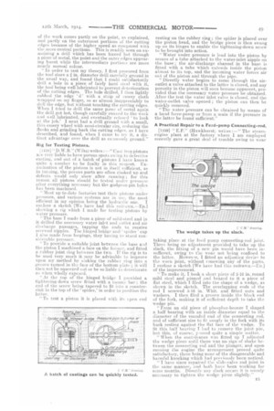
[1159] " E.P." (Hawkherst) writes :—" The steamengine plant at the factory where I am employed recently gave a great deal of trouble owing to wear taking place at the feed pump connecting-rod joint. There being no adjustment provided to take up the slack, the fitting of a new pin would have been insufficent, owing te the wear not being confined to the latter, However, I fitted an adjusting device to the worn joint, without renewing any of the parts. I enclose a sketch [We have had this redrawn.—Enel of the improvement.
"To make it, I took a short piece of 5-16 in. round mild steel and pinned and brazed to it a piece of flat steel, which I filed into the shape of a wedge, as shown in the sketch. The overlapping ends of the rod I screwed 5-16 in. Whit, and fitted nuts and washers. I then filed a groove inside the block end of the fork, making it of sufficient depth to take the wedge pin.
"From an old piece of phosphor-bronze I shaped a half bearing with an inside diameter equal to the diameter of the rounded end of the connecting rod, and of sufficient size to fit snugly in the fork with its back resting against the flat face of the wedge. To fit this half bearing I had to remove the joint pin, but this, of course, 'roved quite a simple matter.
" When the contrivance was fitted up I adjusted the wedge piece until there was no sign of shake between the connecting rod and the plunger, a-nd upon running the engine the arrangement preyed quite satisfactory, there being none of the disagreeable and harmful knocking which had previously been noticed.
" I have since repaired the slide-valve rod joint in the same manner., and both have been working for some months. Directly any slack occurs it is merely necessary to tighten the wedge piece slightly."