


Chain-drive for Battery-electrics
Page 70
If you've noticed an error in this article please click here to report it so we can fix it.
ATRANSMISSION arrangement intended mainly for three-wheeled battery-electric vehicles, is shown in patent No. 689,339, by T. Jervis and Mickleover Transport, Ltd., Twyford Works, Whitby Avenue, London, N.W.10. The chief feature is that the
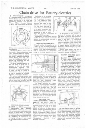
driN log motor is mounted directly over the back axle.
The drawing shows a rear-end view of the chassis. A channel-sectioned beam (1) is clamped under the springs and is shaped to clear the axle; it also forms a recess for housing the electric driving motor (2). The motor is pivoted about point 3 to provide an adjustment for the length of the chain (4).
The latter transmits the drive to the axle which is fitted with a sprocket in lien of the usual propeller-shaft coupling. The sprocket is mounted on a number of studs (5) each of which is surrounded by a sleeve of rubber, so that a measure of torsional resilience is imparted to the drive.
The scheme enables a standard back axle to be employed, and has the advan tage that by removing the spring clamps and the motor leads the entire unit can be quickly removed for maintenance.
PATENT No. 689,480, comes from I Daimler-Benz A.G., StuttgartUntertfirkheim, Germany, and deals with an improved cylinder-head layout, suitable for either spark or compression-ignition engines. It is claimed that the arrangement is very favourable from the standpoint of combustion and scavenging technique; it also simplifies the construction of the engine.
A36 Referring to the drawing, the valves are worked by a pair of camshafts via rockers (1). The combustion space (2) is approximately hemispherical and leads to the cylinder via a narrow neck (3). The piston is a close fit at top stroke, so that the bulk of the gas is compressed into the combustion space. Good scavenging is said to result from the co-axial arrangement of exhaust and inlet passages.
Accessibility is exceptionally good; to grind in the valves it is not necessary to remove the cylinder-head, but only a second lid-like head (4).
FABRICATED BACKPLATES
TN small vehicles, the backplatc V the I brake not only takes reaction stresses but also functions as a dirt-excluding closure. With large vehicles however, such a construction is uneconomic owing to the large quantity of thick
material employed. A two-part construction, using lightand heavy-gauge steel where most suitable, is shown in patent No. 689,017, by Automotive Products Co., Ltd., Tachbrook Road, Leamington Spa, Warwickshire.
The design embodies an 8-gauge carrier (1) to deal with the mechanical stresses; this is attached to a pressing (2) made of 16-gauge steel. The two parts are united by numerous spotwelds, and additional bosses (3) may be welded on to receive shoe-steady pins (not shown). A pressed-steel pot, also not shown, may be welded on about the centre to act as an oil-catcher, the oil being drained via holes (4).
STEERING FOR FORWARD-CONTROL VEHICLES
PATENT No. 689,827, refers to vehicles in which the driver's seat is placed above or in front of the front axle, a layout in which it is often difficult to find room for the drop-arm without bringing it dangerously near to
ground level. The patent shows a steering arrangement in which the arm is placed above the axle, and swings in a horizontal plane instead of the usual vertical. The patentee is Miag
Fah rzeugbau, G.m.b.H.. OverRamstadt. Germany. At the bottom of the column is a gearbox (1) having a pair of one to one bevels to take the drive rearwards. The usual reduction box is situated at point 2 and arm 3 is ball-jointed directly to the two track rods (4), the whole arrangement being above axle level. A further advantage is that it is equally suitable for rightor lefthand drive without changing any of the components.
Another claim made is that only a small part of the steering mechanism is exposed to damage by collision.
SUCTION-OPERATED SERVO BRAKES DATENT No. 687,658 comes I from Clayton Dcwandre Co., Ltd., Titanic Works, Lincoln, and shows an improved construction of a vacuum-assisted hydraulic brake.
The drawing shows one of two arrangements described. The pipe from the pedal cylinder is led to the inlet (1) whilst the other connection (2) leads to the wheel cylinders. A vacuum cylinder (3) of the well-known type is located coaxially with the brake cylinder (4).
In operation, when pressure arrives from the pedal cylinder it is applied to space 5 and to the plunger (6). The latter works a lever (7) controlling a vacuum valve (not shown). This valve is provided with a flexible diaphragm which creates a reaction proportional to the vacuum, ahd this is transmitted back to the driver via his pedal.
The valve applies suction to space 8 and the piston is forced to the left. Its rod (9) has a coned end which closes a hollow piston (10), and then forces the piston to the left, applying amplified force to the brakes. Should the vacuum system fail, the manually applied pressure can still reach the brakes via the hollow piston.