


A PNEUMATIC SUSPENSION.
Page 70
If you've noticed an error in this article please click here to report it so we can fix it.
A R6sume of Recently Published Patent Specifications.
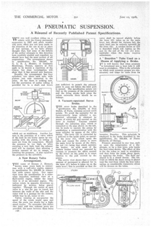
vurE can well recollect riding on a V V vehicle with the Cowey pneumatic suspension in 1007 and often wonder why more effort has not been made in the direction of the use of air in place of leaf spring, as we haVe. always thought that, had some of the 'defects of the earlier attempts in this direction been carefully studied and remedied, we should have had the most perfect of all suspensions. The arrangement shown in specification No. 280,547, by 0. L. R. J. Messier, of Gambetta MonttougeP France, appears at first sight to be merely a repetition of the Cowey, but close investigation will, show that it has several new features.
Broadly, the arrangement has four cylinders, two above each axle, with pistons and rods connected to the axles. So far there is nothing new, but the prevention of undue rolling is provided for in a shaft and levers which act as stabilisers. Another feature is the provision of a valve which if the load be too heavy opens by contacting with the piston, so letting in more air from the compressor. Should the pressure be too high, as when carrying a very light load, the exhaust port will be exposed, thus allowing a certain amount of air to escape, so lowering the pressure. A pipe equalizes the pressure in the cylinders.
A New Rotary Valve Arrangement.
TflE name of Horace J. Howard,
known some years back in connection with a cuff-valve engine, appears in specification No. 280,391 in connection with rotary valves. Our upper view from the specification is a somewhat imperfect sectional view of • a fluid-cooled engine, whilst the lower view is of an air-cooled engine. The valves rotate in opposite directions as indicated by arrows, being geared together. Through the centre of each valve is a slot for gas to travel, but between the walls of the slot and the outer wall is a passage for the coolant, which may be oil, water or air.
Valves rotating at one-quarter the speed of the crank would open and close the ports too slowly for a highspeed engine. To overcome this defect two inlet miff two 'exhaust ports are provided, the space between them being c48
just sufficient to permit the exhaust gases to pass out before the inlet port is opened. The specification points Out that as the pressure of the compression and the firing stroke both press the valves outwards there should be no leakage.
A Vacuum-operated Servo Brake.
THE servo brake described in the
specification No. 274,084, of Paul Rallot, of Paris, contains several novel points. To avoid the necessity for an inconveniently large cylinder a mechanical advantage is obtained by means of which the pull exerted on the lever is doubled. Vacuum created through the induction pipe, which is connected to the pipe shown on the left, can be made to operate the piston by establishing a communication with the large cylinder by means of the valve shown. The lever (B) is connected by a pull-rod to the brake pedal, so operating the lever (C), which opens the valve and causes the piston to move the main lever by means of the chain, the rod (A) being that which operates the brakes. As with most of the modern brakes which are operated by vacuum or pressure the effort exerted by the driver on his pedal is in exact relation to the pull exerted by the Piston.
The centre view shows that a certain amount of movement is allowed for in the lever (C) before it takes up on the main lever ; this is provided so that the valve shall be 'opened slightly before the lever (0) takes up on the main lever, but, should the vacuum fail, the main lever can be entirely 'operated ..by the lever (B). A ratchet device at (D) is described which will tighten up the nut • on the end of the rod (A) automatically when the brake requires adjustment.
A Bourdon" Tube Used as a Means of Applying a Brake. IT is well known that when pressure
is introduced into a bent tube it will tend to straighten. This is the principle on which most pressure gauges are constructed, and takes its name from its inventor, Bourdon. This principle is employed in the brake described in the specification, No. 288,454, of Pierce Richards, of Chicago.
Pressure generated in any way, such as upon the compression of a diaphragm, or by a foot lever, acts inside the bent tubes shown. The effect of this is for the tubes to tend to straighten and thus force the brake shoes apart, so applying the brake. The fluid employed is in a closed circuit. The fulcrum on which the shoes swing is placed near the root from which the bent tnbes spring, so considerable transverse stress will be thrown on the tubes.