


Patents Completed.
Page 30
If you've noticed an error in this article please click here to report it so we can fix it.
Complete specifications of the following patents will be sent to any address in the United Kingdom; by the Sales Branch, Patent Office, Holborn, W.C., upon receipt of eightpence per copy.
A Crossley Combustion Chamber.
K. I. Crossley, and W. Le P. Webb, No. 10,202, dated 30th April, 1912.—In a horizontal four-stroke internal combus
tion engine using oil as fuel, the combustion chamber is separate from, but communicates with, the working cylinder by a contracted neck. The special feature of this engine is that this neck is placed at the lowest part of the cylinder, and the exhaust valve is arranged in the bottom of the combustion chamber, so that any oil which tends to lie in the combustion chamber is swept out by the exhaust If it be desired, the combustion chamber may be made even lower than the cylinder itself. The exhaust and inlet valves are preferably arranged on a vertical axis, one above the other, in which case the vaporizer cap is fitted to the end of the combustion chamber.
An Automatic Carburetter Jet.
C. IL Claudel, No. 10,638112, dated under International Convention, 6th May, 1911.—This specification describes some modifications in the carburetter forming the subject-matter of Patents Nos. 6870/08 and 23,287/08. The lower part of the jet nozzle is surrounded by a
double jacket, through which the air is drawn in such a way as to create a. difference in pressure between the discharge opening of the main tube and the inlet opening. The new feature consists of a diaphragm inserted in the nozzle below the normal level of the liquid, and two openings which are provided, one above
and one below the diaphragm through which the fuel can pass out. Both of these openings are below the level of the fuel. The action of this carburetter is described at some length in the specification, in which it is explained how one fuel orifice provides the main fuel supply at low speeds, while the other provides it at high speeds.
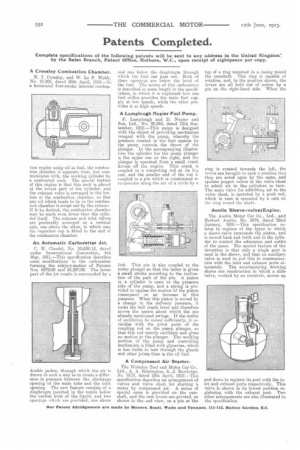
A Lamplough Napier Fuel Pump.
Lamplough and D. Napier and Son, Ltd., No. 20,954, dated 13th September, 1012.—This pump is designed with the object of providing mechanism integral with the pump, whereby the pressure created in the fuel system by the pump controls the throw of the plunger. In the accompanying illustration the cylinder for the pump plunger is the upper one on the right, and the plunger is operated from a small crank driven off the engine. This crank is coupled to a connecting rod at its big end, and the smaller end of the rod is coupled to a pin which is constrained to reciprocate along the arc of a circle by a
link. This pin is also coupled to the pump plunger so that the latter is given a small stroke according to the inclination of the path of the pin. A piston in a cylinder is open to the pressure side of the pump, and a spring is provided to oppose the motion of the piston consequent on an increase in this pressure. When this piston is moved by a change in the delivery pressure, it rocks the bell crank lever and therefore moves the centre about which the pin already mentioned swings. If the centre of oscillation be raised sufficiently, it coincided with the pivot point of the coupling rod on the pump plunger, so that this rod merely oscillates and gives no motion to the plunger. The working portion of the pump and controlling mechanism is filled with glycerine, which is less liable to leak through the glands and other joints than is the oil fuel.
A Compressed Air Starter.
The WoIseley Tool and Motor Car Co., Ltd., A. A. Remington, A. J. Rowledge, No. 0113, dated 18th April, 1012.—This specification describes an arrangement of valves and valve chest for starting a motor by compressed air. A series of special cams is provided on the camshaft, and the cam levers are pivoted, as shown in the end view, on a pin at the
top of a ring mounted in a casing round the camshaft. This ring is capable of rotation, and, in the position shown, the levers are all held out of action by a pin on the right-hand side. When the ring is rotated towards the left, the levers are brought to such a position that they are acted upon by the cams, and operate poppet valves in the valve chest to admit air to the. cylinders in turn. The main valve for admitting air to the valve chest, is operated by a push rod, which in turn is operated by a cam on the ring round the shaft.
Austin Sleeve-valve I Engine.
The Austin Motor Car Co., Ltd., and Herbert Austin, No. 1674, dated 22nd January, 1910.—This specification relates to engines of the types in which a sleeve-valve surrounds the piston, and is moved back and forth and in the cylinder to control the admission and outlet of the gases. The special feature of the invention is that only a single port is used in the sleeve, and that an auxiliary valve is used to put this in communication with the inlet and exhaust ports alternately. The accompanying drawing shows one construction in which a slide valve, worked by an eccentric, moves up and down to register its port with the inlet and exhaust ports respectively. This valve is shown in its lowest position registering with the exhaust port. Two other arrangements are also illustrated in, the specification.