


An American Two-speed Back Axle
Page 58
If you've noticed an error in this article please click here to report it so we can fix it.
A Resume of Patent Sped fications that Have Recently Been Published
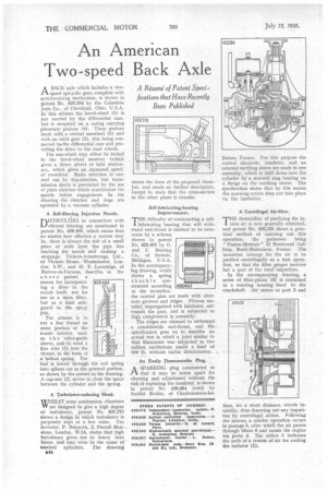
ABACK axle which includes a twospeed epicyclic gear, complete with synchronizing mechanism, is shown in patent No. 429,284 by the Columbia Axle Co., of Cleveland, Ohio, U.S.A. In this scheme the bevel-wheel (1) is not carried by the differential case, but is mounted on a casing carrying planetary pinions (4). These pinions mesh with a central sunwheel (3) and with an orbit gear (2), this being connected top the differential case and providing the drive to the road wheels.
The sun-wheel may either be locked to the bevel-wheel member (which gives a direct drive) or held stationary, which gives an increased speed, or overdrive. Ratio selection is carried out by dog-clutches, but transmission shock is prevented by the use of plate clutches which synchronize the speeds before engagement. In the drawing the clutches and dogs are operated by a vacuum cylinder.
A Self-filtering Injection Nozzle.
nIFFICULTIES in connection with
efficient filtering are mentioned in patent No. 429.405, which states that no matter how effective a system may be, there is always the risk of a small piece of scale from the pipe line reaching the nozzle and causing a stoppage. Vickers-Armstrongs, Ltd., of Vickers House, Westminster, London. S.W., and H. T. Loveridge, of Barrow-in-Furness, describe, in the above patent, a means for incorporating a filter in the nozzle itself, not for use as a main filter, but as a final safeguard to the spray jets.
The scheme is to cut a fine thread on some portion of the nozzle interior, such as t h e valve-guide sleeve, and towind a fine wire (1) into the thread, in the form of a -helical spring. The fuel is forced through the coil spring into splines cut in the screwed portion, as shown by the arrows in the drawing. A cap-nut (2) serves to close the space between the cylinder and the spring.
A Turbulence-reducing Head.
WHILST some combustion chambers VY are designed to give a high degree of turbulence, patent No. 429,378 shows a design in which turbulence is purposely kept at a low value. The inventor, P. Belyavin, 2, Purcell Mansions, London, W.14, states that high turbulence gives rise to heavy heat losses, and may "even be the cause of cracked cylinders. The drawing
344 shows the form of the proposed chamber, and needs no further description, except to state that the cross-section in the other plane is circular.
Self -lubricating-bearing Improvements.
THE difficulty of constructing a self!. lubricating bearing that will withstand end-thrust is claimed to be overcome by a scheme_ shown in patent No. 429,403 by 0. and S. Bearing Co., of Detroit, Michigan, U.S.A. In the accompanying drawing, which shows a spring shackle constructed according to the invention, the central pins are made with alternate grooves and ridges. Fibrous material, impregnated with lubricant, surrounds the pins, and is subjected to high compression in assembly.
The ridges are claimed to withstand a considerable end-thrust, and the specification goes on to describe an actual test in Which a. joint similar to that illustrated was• subjected to two million oscillations under a load of 200 lb. without undue_ deterioration. 1111111111111111
424403 An Easily Demountable Plug. •
A SPARKING plug constructed so Pl. that it may be taken apart for cleaning and adjustment Without the risk of rupturing the insulator, is shown in patent No. 428,884 (void) by Societe Roddo, of Charbonnieres-les
Baines, France. For this purpose the central electrode, insulator, and an external earthing sleeve are made in one assembly, which is held down into the cylinder by a screwed ring bearing on a flange on the earthing sleeve. The specification states that by this means the screwing action does not take place on the insulation.
A Centrifugal Air-filter.
THE desirability of purifying the intake air is now generally admitted, and patent No. 429,153 shows a practical method of carrying out this operation, the patentees being " Fusion-Moteurs " of Boulevard Gallieni, Rueil-Malmaison, France. The inventors arrange for the air to be purified centrifugally as a first operation, so that the filter proper receives but a part of the total impurities.
In the accompanying drawing, a series of filter-plates (6) is contained in a rotating housing fixed to the crankshaft. Air enters at port 2 and then, for a short distance, travels inwardly, thus throwing out any impurities by centrifugal action. Following the arrows, a similar operation occurs in passage 5, after which the air passes through filters 6 and enters the engine via ports 4. The orifice 3 indicates the path of a stream of air for cooling the radiator (1).