


An Engine Indicator Without Inertia Inaccuracies
Page 35
If you've noticed an error in this article please click here to report it so we can fix it.
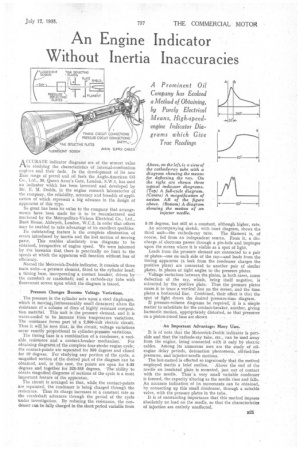
A Prominent Oil Company has Evolved a Method of Obtaining, by Purely Electrical Means, High-speedengine Indicator Diagrams which Give True Readings
ACCURATE indicator diagrams are of the utmost value in studying the characteristics of internal-combustion engines and their fuels. In the development of its new Esso range of petrol and oil fuels the Anglo-American Oil Co., Ltd., 36, Queen Anne's Gate, London, S.W.1, has used an indicator which has been invented and developed by Mr. E. M. Dodds, in the engine research laboratories of the company, the reliability, accuracy and breadth of application of which represent a big advance in the design of apparatus of this type.
So great has been its value to the company that arrangements have been made for it to be manufactured and marketed by the Metropolitan-Vickers Electrical Co., Ltd., Bush House, Aldwych, London, W.C.2, in order that others may be enabled to take advantage of its excellent qualities.
Its outstanding feature is the complete elimination of errors introduced by inertia and the lost motion of moving parts. This enables absolutely true diagrams ' to be obtained, irrespective of engine speed. We were informed by the inventor that there is practically no limit to the speeds at which the apparatus will function without loss of efficiency.
Named the Metrovick-Dodds indicator, it consists of three main units—a pressure element, fitted to the cylinder head; a timing base, incorporating' a contact breaker, driven by the camshaft or crankshaft; and a cathode-ray tube with fluorescent screen Upon which the diagram is traced.
Pressure Changes Become Voltage Variations.
The pressure in the cylinder acts upon a steel diaphragm, which in moving (immeasurably small distances) alters the resistance of a column of discs of highly resistant composition material. This unit is the pressure element, and it is water-cooled to be immune from temperature variations. The resistance forms part Of a 2,500-volt electric 'circuit. Thus it will be seen that, in the circuit, voltage variations occur exactly proportional to cylinder-presstite "variations.
The timing base is a combination of a condenser, a variable resistance and a contact-breaker mechanism: For obtaining diagrams of the complete four-stroke engine ,cycle; the contact-points are separated for 350 degrees and closed for 10 degrees. For studying any portion 'of the cycle, a magnified section of the desired part of the diagram can be obtained, and, in this case, the points are open for 5-35 degrees and together for 325-355 degrees. The ability to obtain Magnified diagrams of sections of the cycle is a most important feature of the apparatus. . The circuit is arranged so that, whilc the contact-points are separated, the condenser is being charged through the resistance. Thus its Charge increases at a constant rate as the crankshaft advances through the period of the cycle under investigation. By reducing the resistance, the condenser can be fully charged in the short period variable from 5-35 degrees, but still at a constant, although higher, rate. An accompanying sketch, with inset diagram, shows the third unit—the cathode-ray tube, The filament is, of course, fed from an independent source. From it, a discharge of electrons passes through a pin-hole and impinges upon the screen where it is visible as a spot of light.
Leads from the pressure element are connected to a pair of plates—one on each side of the ray—and leads from the timing apparatus (a leak from the condenser charges the positive plate) are connected to another pair of similar plates, in planes at right angles to the pressure plates.
Voltage variations between the plates, in both cases, cause deflection of the ray; which, being itself negative, is attracted.by the positive plate. • Thus the pressure plates cause it to trace a vertical line on the screen, and the time plates a horizontal line: Combined, their effect is that the spot of light draw's the desired ,pressure-time diagram.
If pressure-volume diagrams be ' required, it is a simple matter to substitute for the contact-breaker, another, giving harmonic motion, appropriately_ distorted, so that presstires on a piston-travel base are shbwn • An Important Advantage: Many Uses.
It is of note that the Metrovick-Dodds indicator is portable and that the cathode-ray tube, etc., can be used away from the engine, being connected with it only by electric cables. Aniong its numerous uses are the study of oil. engine delay periods, detonation phenomena, oll-fuel-hne pressures, and injector-needle motions. ' • The last-named is effected so ingeniously that the method employed merits a brief outline. Above the end of the needle an insulated plate is mounted, just out of contact with the needle. Thus a very small variable condenser is formed, the capacity altering as the needle rises and falls. An accurate indication of its movements can be obtained, by connecting up this small Condenser, through a suitable valve, with the pressure plates in the tube..
It is of outstanding importance that this method imposes absolutely DO load on the needle, so that the characteristics of injection are entirely unaffected.