


AN AUTOMATIC BRAKE ADJUSTMENT.
Page 68
If you've noticed an error in this article please click here to report it so we can fix it.
A Resum6 of Recently Published Patent
Specifications.
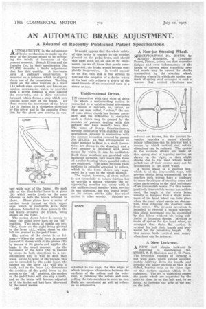
A ITTOMATICITY in the adjustment 1-1,of brake mechanism to make up for wear of the linings seemsto be occupying the minds of inventors at the present moment. Joseph Dixon and the Daimler Co., in their specification No. 271,926, describe a brake adjustment that has this quality. A foot-brake lever of ordinary construction is mounted on a fulcrum which is slightly above one of the cross-tubes. Working freely on the same fulcrum is a lever (A) which rises upwards and has an extension downwards, which is provided -with a screw forming a stop against the cross-tube, and a third extension forward, which forms a. stop which acts against some part of the frame. By these means the movement of the lever (A) is limited in a clockwise -direction by the screw and in the opposite direction by the short arm coming in con
tact with -part of the frame. On each side of the foot-brake lever is a plate (B) which_ works freely on the same fulcrum as both the levers referred to above. These plates have a series of ratchet teeth formed on their upper edge which is concentric with their fulcrum. Attached to these plates is the rod which actuates the brakes, being shown on the right.
The spring shown below is merely to bring the pedal lever back to its "off" position. Two pairs of pawls are provided, those on the right being pivoted to the lever (A), whilst those on the left are pivoted to the pedal lever.
The action of the device is as fullows :—Where the pedal lever is pressed forward it draws with it the plates (B) by means of its pawls and applies the brake in the usual manner. As the movement of the lever (A) is limited by steps in both directions to a predetermined are, it will be seen that when, owing to wear of the linings, this are in exceeded by the pedal lever, the ratchet on the lever (A) will slip a tooth, and as the lever (A) determines the position of the pedal lever on its return to the " off " position, the ratchet on the pedal lever will also slip a tooth. and so the brake will become adjusted as if the brake rod had been shortened by the usual means.
• c46 It would appear that the whole safety of this brake is trusted to the ratchet pivoted on the pedal lever, and should this pawl stick up on one of its movements (as we all know that pawls sometimes do), the brake would become com pletely inoperative. It would appear to us that this risk is too serious to warrant the adoption of a device which at its best only relieves a driver of the small trouble of an occasional turn of a screw or nut.
Unidirectional Drives.
TN connection with that class of drive in which a reciprocating motion is converted to a unidirectional moven:tent, by means of ratchets, or, rather, as they are now called, "valves," the use of some silent clutch has become necessary, and the difficulties in designing such -a clutch may be gauged by the number of patents dealing with this subject that have recently been filed.. The name of George ConAantinesco, already associated with clutches of this description, appears in connection with the present invention covered by patent No. 271,572. In this arrangement an outer member is fixed to a shaft (serrations are shown in the drawing) and a free member is provided with some means by which it can be oscillated. Both these members are provided with hardened surfaces, very much like those of a roller bearing where parallel rollers are employed. The space between these surfaces is actually occupied by rollers, which in the form shown are separated by a cage in the usual manner.
The object, however, of these rollers is not essentially to reduce friction but to provide a means whereby the reciprocating member can 'carry with it the unidirectional member when moving in one direction, but can travel freely on its return stroke .(the free-wheel
action in other wordS), Springs are
attached to the cage, the thin edges of which interpose themselves between the • surfaces of the rollers and the outer race, SO jamming the rollers and compelling the to members to move as one. Balls are mentioned as well as rollers as an alternative.
A Non-jar Steering Wheel.
SPECIFICATION No. 254,734, by Maurice Houdaille, of LevalloisPerrot, France, points out that muscular fatigue and even inflammation of the hands of drivers when travelling over bad roads may be caused by shocks transmitted by the steering wheel. Steering wheels in which the spokes arc made of spring steel arranged in such a manner that vertical vibrations are
reduced are k-nowu, but the pres'ent in-section provides a means whereby iotary vibrations can be relieved and g means by which vertical and rotary, vibrations can be reduced. The spokes in the example shown are made of. thin spring steel of tapering section, as shown on the 'right, so that slight shocks due to -the road wheels being jerked 'out of their course may not be transmitted to the hand wheel.
A worm wheel in a steering box, which is of the irreversible type, will prevent shocks being transmitted, but in practice such worms have a tendency to cause breakages of steering arms and other parts owing to the rigid resistance of an irreversible worm. For this reason positively irreversible worms are seldom used, the angle of the worm being usually so designed that a slight movement of the hand wheel can take place when the road wheel meets an obstruction, thus relieving the steering arms from stress. The present invention is intended to Provide a means whereby this slight movement can be controlled by the driver without his being subjected to fatiguing shocks. Mention is made of spokes for the hand wheel, so arranged that their flat section is vertical for 'half their length and horizontal for the remaining length. By this means both vertical and rotary vibrations can be reduced.
A New Lock-nut.
A NEW and simple lock-nut is described in specification No. 270,357, S. F. Marsden and C. E. Place. The invention consists of forming a nut with slots, which extend approximately halfway down. its length, and forming the under surface so that it is dished, hearing only on its outer edge on the surface against which it is tightened. The act of tightening causes the parts which are separated by the slots to close in on the bolt and, in so to increase the griji Of the nut on the bolt.