


Gear-hardening Technique
Page 72
If you've noticed an error in this article please click here to report it so we can fix it.
INDUCTION heating is ideal for gear 'hardening, beeause only the skin of the teeth is heated and' quenched, thus eliminating distortion in thebody of the .gear.. The temperature gradient between the skin and the mass of the metal can.
• however, be too steep, which leads to non-uniformity in the depth of hardening. To overcome this by incorporating a slight 'pre-heat in the process, is the . basis. of. patent No. 642,865, which comes from Morris Motors, .Ltd., Court, house Green, Coventry.
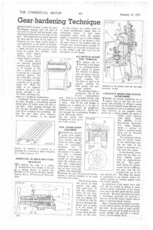
The drawing shows the specially designed . machine used. The gear to be treated, in this _case a helical one (1)% is placed on a mandrel • between centres, and the lathe-like carriage (2) is arranged to slide vertically on an upright
' guide (3). With the slider at its topmost position, the gear (irst passes through a coil t4) which pre-heats the teeth to a moderate temperature.
Continued downward motion moves the gear through a close-fitting second heater-plate (5) which raises the skin to red heat. After passing through this coil, the gear descends into a quenching tank (6) to complete the hardening So that the gear shall move helically through the notches in the second heater, its mandrel is rotated as it . descends by 4 stationary finger engaging in • a helical groove (7).
IMPROVED RUBBER-MOUNTED SHACKLES
TO deform the ends of a rubber shackle-bush into flanges is the aim ,2f a design shown in patent No. -Z41,990, by H. Claykin-Wright, Wellesbourne House, Wellesbourne, Warwick' shire. In this scheme, the rubber bush (I) is made considerably longer than its containing sleeve, so that when assembled under force, • the Surplus length is squeezed out to form flanges (2). The essence of the patent is that the inner faces of the shackle links are formed into saucer-Shaped recesses (3) which impart an inwardly directed force to the rubber, and thus assist in the formation of the flange.
ALUMINIUM FLOOR FOR VEHICLES
TO replace oak for flooring is the object of an aluminium-alloy floor shown in patent No. 643,921, by Bonallack and Sons, Ltd., St. George Works, Cable Street, London, E.1. The floor is said to be equally suitable for both goods and passenger vehicles.
The drawing shows a perspective view of the ba sic constructional unit. This is an extruded section, and is ribbed on its upper surface to provide a tread. One of the end flanges is stepped up, as shown at 1, so that in assembly it overlaps its neighbour, which is flat as shown at 2. Screws are put through the overlapping flanges, a wood filler-strip covering the screws and bringing the level up to the tread surface.
NEW COMBUSTION CHAMBER
PATENT No. 643,619, comes from Oesterreichische Saurer-Werke A.G., Vienna, and discloses the latest suggestions for combustion chambers for oil engines. According to the patent, it is imperative that a chamber formed in the piston should be symmetrical about the cylinder axis, and this requirement often leads to the adoption of four valves per cylinder, thus materially itcreasing the cost. The enables a central chamb with only two valves,
plesent scheme er to be used
The drawing shows the layout in both section and plan, The inlet-valve (1) and the exhaustervalve (2) are positioned to one side, and the injector (3) is placed so that its jet axis intersects the piston axis at point 4 in the centre of the chamber. . The arrows show the directiOn of the swirl
CONSTANT SPEED FOR ENGINE AUXILIARIES
THERE are certain auxiliaries on an I engine, such as the fan, the water pump and possibly an oil-servo pump, all of which could be more efficient were they designed to run at a constant speed. This, however, is not possible when driven by a vehicle engine, the speed of which varies between wide limits. Patent No. 644.096, from Servo-Frein Dewandre S.A., Liege, Belgium, shows a scheme . by which a constant-speed drive can be obtained for these units.
The proposed scheme uses an electric motor as the controlling unit, but the bulk of the power is provided by a belt from the engine.
In the drawing, which shows the fan only, the drive initially comes from an engine-driven
belt (1). The pulleyshaft drives the planetcarrier (2) of a differential gear, and the fait
is driven by one of the sun pinions (3). The other sun pinion is connected to an electric motor -(4), which receives its current supply from the vehicle battery.
In operation, if the motor were held still, the fan would be driven at twice normal Speed; conversely, if the motor were run at double speed, the fan would stand still. Between these ttvo'extremeS, a centrifugal governor (5)controls .a rheostat (6) in. the motor circuit, and so
gives a constant-speed control.. . Only a fraction of the actual load falls • on the electric motor, the belt provicling the bulk. In the event of total eleetric failure, a pin (7) can be ,used to lack the motor spindle and provide. a conventional variable-speed :drive.