


OPERATING A BRAKE BY FLUID PRESSURE.
Page 32
If you've noticed an error in this article please click here to report it so we can fix it.
A Résumé of Recently Published Patent Specifications.
brakes which are operated by means of fluid pressure acting on a piston within a cylinder, it has been found essential that the amount of pressure exerted on the brakes should be proportionate to that brought to bear on the pedal by the driver; in other words, the driver should be able to " feel " how hard he is applying his brakes, otherwise he may experience a skid.
Another important point now recognized in the design of such brakes is that some provision should be made so that the driver can stop his vehicle entirely by means of his foot pressure, should the pressure from the fluid fail through any cause.
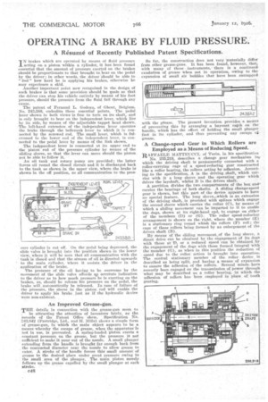
The patent of Fernand L. Godesu, of Ghent, Belgium, No. 243,588, embodies these essential points. The pedal lever shown in both views is free to turn' on its shaft, and is only brought to bear on the independent lever, which lies by its side, by means of the adjustable tappet head shown. The left-hand extension of the independent lever operates the brake through the hellcrank lever to which it is connected by the screwed red. The small lever, which is fulCrumed to the lower end of the independent lever, is connected to the pedal lever by means of the link shown.
The independent lever is connected at its upper end to the piston rod of the pressure cylinder by means of the sliding sleeve, so that the lever can move should the piston not be able to follow it. •
An oil tank and rotary pump are provided ; the latter forces oil round the closed circuit and it is discharged back to the tank as shown in the upper view, where the brake is shown in the off position, as all communication to the pres
sure cylinder is cut off. On the pedal being depressed, the slide valve is brought into the position shown in the lower view, where it will be seen that all communication with the tank is closed and that the stream of oil is directed upwards to the main cylinder, where it assists the driver in the application of the brake.
The pressure of the oil having to be overcome by the movement of the slide valve affords ap accurate indication to the driver as to how much pressure he is exerting on the brakes, as, should he release his pressure on the pedal, the brake will ,autemstically be released.. In case of failure of the pressure, the sleeve in the 'piston rod will enable the driver to apply his brake. just as if the hydraulic device were non-existent.
An Improved Grease-gun.
THE details in connection with the grease-gun seem to , be attracting the attention of inventors lately, as the records of the Patent Office 'show. Specification No.
243,842 (Partridge, Ltd., and H. Mills) shows a simple form of grease-gun, in which the main object appears to be a means whereby the escape of grease, when the apparatus is not in use, is prevented. A spring-loaded piston exerts a constant pressure on the grease, but the pressure is not
• sufficient to make it pour Out of the nozzle. A small plunger extending from the handle is brought far enough back from the contracted diameter near the nozzle to allow grease to enter. A stroke of the handle forces this small amount of grease to the desired place under great pressure owing to the small area of the plunger. The main piston merely follows up the grease expelled by the small plunger at each stroke. • • So far, the construction does not very 'materially differ from other grease-guns. It has been found, however, that, with many of these • instruments,. there is a continued exudation of grease When not in operation, owing to the expansion of small air babbles that have been entrapped
with the gfease. The present invention provides a means of preventing this by arranging a bayonet catch on the handle, which has the effect of holding the small plunger gfarestase.
in its cylinder, and thus preventing any escape cri•
A Change-speed Gear in Which Rollers are Employed as a Means of Reducing Speed.
RAFFAELE MATTEUCCI, of Turin, in his specification No. 235,218, describes a change gear mechanism inv which the driving shaft is permanently connected with a roller-carrying cage of a speed-reducing gear constructed like a roller bearing, the rollers acting by adhesion. According to the specification, A is the driving shaft, which carries with it a long sleeve and' the operating gear which drives the layshaft, whilst B is the driven shaft.
A partition divides the two compartments of the box andcarries the bearings of both shafts. A sliding changespeed gear is shown, but this part of the device appears to have no special feature. The long sleeve,-..which is an extension of the driving shaft, is provided with splines which engage. the second sleeve. which carries the collar (C), by means of which a sliding movement can be 'imparted to it to enable the dogs, shown at its right-hand epd, to engage on either of the members (I)) or (G). The roller speed-reducing arrangement is shown on the right, where the member (E) is a stationary ring roUnd which the rollers (F) roll the cage of these rollers being formed by an enlargement of the driven shaft (B).
By means of the sliding movement of the long sleeve, a direct drive can be obtained by the engagement of its clogs with those at D. or a reduced speed can be obtained by the engagement of the dogs with those formed integral with the member (G), as 'when in this position the reduction of speed due to the roller action is brought into operation. The central stationary member of the roller device is described as being split, and having a means of expansion to ensure the adhesion of the rollers. Several minds have recently been engaged On the transmission of power through what may be described as a roller bearing, iv which . the • adhesion of rollers has been employed in place of tooth gearing.