


Precise Pump Control
Page 80
If you've noticed an error in this article please click here to report it so we can fix it.
A CENTRIFUGAL governor that Pi, adjusts both the quantity of fuel injected and the timing of the charge is covered by patent No. 818,699. (Robert Bosch, G.m.b.H., 4 BreitSeheidstrasse, Stuttgart-W, Germany.)
The drawing shows the layout of the components attached to the injection pump (1). • A centrifugal governor (2) performs two functions; it works the rack-rod (3) of the injection pump and also a needle valve in a hydraulic junction (4).
The needle valve controls the pressure applied to a spring-loaded hydraulic piston (5). The pressure is provided by the fuel itself from the feed pump (6). The hydraulic piston moves a sliding collar -(7) included in the pump drive. The collar and its associated shafts have rightand left-handed helical splines, so that movement to the right or left
COLD PROTECTION
PATENT. No. 818,514 shows a means for keeping warm both the engines and passenger spaces of vehicles parked in the open over long, periods. (R. Nilsson, Bogatan 41c, Gothenburg, Sweden.) .
It is propOsed to connect vehicles by permanently installed piping to a central boiler. The drawing shows the layout,. in which 1 is a heat-exchanger. and 2 a driving pump. The vehicles are in parallel connection for flow and return, and each engine is provided with a small heat-exchanger; a similar unit being fitted inthe body.
The pipe layout is such that the normal radiators of the vehicles are not in the main cireuit. This prevents wasteful dissipation of heat. They are, however, prevented from freezing by a restricted flow of hot water.
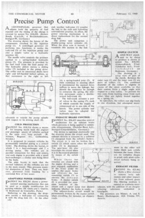
ADAPTABLE POWER STEERING PATENT No. 826,241 shows a powerassisted steering mechanism that can be used as a simple modification for existing vehicles. (M. Onde and J. Guerin, 72 Boulevard de Courcelles, Paris.) -Referring to the drawing, the droparm carries a ball-joint (1) connecting it with the drag link (2). At the other
r46 via a, spring-loaded joint (5). If little resistance to steering effort is encountered the manual .force suffices to move the linkage, but should the resistance be enough to compress the spring, the relative movement rocks a doublearmed bell-crank (6).
The bell-crank actuates a pair of valves in the casing (7), each of which controls the supply of compressed air to one side of the 'piston. The 'power cylinder and valves may be adapted for hydraulic operation.
EXHAUST BRAKE CONTROL 111011ATENT No. 826,435 describes control I mechanism for an exhaust brake which prevents it being applied in unsuitable circumstances. (Daimler-Benz A.G.. Stuttgart-Unterttirkheim, Germany.)
The device is operated electrically and the drawing shows the circuit used. The exhaust throttle is actuated by a solenoid (1) energized from the vehicle's battery. The circuit to it can be broken .by a switch (2) which opens when the clutch pedal (3) is depressed. The gear-lever (4) also interrupts the circuit when it is in the neutral position by means of the switch
(5). • When these two switches are closed with the engine driving and a gear engaged, application of the brake pedal (6) applies the main brake and closes the last remaining switch (7) to operate the exhaust brake. A master switch (8) is provided for complete isolation of , the circuit and a signal lamp (not shown) indicates whether the, brake is ready. '
The exhaust-brake. circuit would be permanently broken by the master switch when travelling, for instance, on slippery roads. AONE-WAY clutch said to be cheap to produce is shown in patent No. 818,502. (Zahnradfabrik Friedrichshafen A.G., Friedrichshafen ant Bodensee, Germany.) The drawing is a scrap view of part of the clutch. Between the outer race (1) and the inner race (2) are pairs of rollers (3); The combined diameter of the rollers is slightly in excess of the space available, so that their: centres form a slight angle with respect to a true radius. To prevent the two rows from backing away from each other, they are lightly biased together by a spring (4).
In operation, the rollers can slip freely in one direction, but attempted move ment in the other will make them jam solidly between the races. There are no complex shapes to grind, only plain cylindrical surfaces being required.
EXHAUST FILTER DATENT No, 825,462 I shows a filter claimed to remove tarry substances and other impurities from exhaust gases. The filtering medium is natural or synthetic meerthe addition of an oxygensubstance embedded in The patentees are Messrs. A. and E. Bauer, Hackengasse, 10/6 Vienna 'XV, Austria.