 1
1 2
2 3
3 4
4 5
5 6
6 7
7 8
8 9
9 10
10 11
11 12
12 13
13 14
14 15
15 16
16 17
17 18
18 19
19 20
20 21
21 22
22 23
23 24
24 25
25 26
26 27
27 28
28 29
29 30
30 31
31 32
32 33
33 34
34 35
35 36
36 37
37 38
38 39
39 40
40 41
41 42
42 43
43 44
44 45
45 46
46 47
47 48
48 49
49 50
50 51
51 52
52 53
53 54
54 55
55 56
56 57
57 58
58 59
59 60
60 61
61 62
62 63
63 64
64 65
65 66
66 67
67 68
68 69
69 70
70 71
71 72
72 73
73 74
74 75
75 76
76 77
77 78
78 79
79 80
80 81
81 82
82 83
83 84
84 85
85 86
86 87
87 88
88 89
89 90
90 91
91 92
92 93
93 94
94 95
95 96
96 97
97 98
98 99
99 100
100 101
101 102
102 103
103 104
104 105
105 106
106 107
107 108
108 109
109 110
110 111
111 112
112 113
113 114
114 115
115 116
116 117
117 118
118 119
119 120
120 121
121 122
122 123
123 124
124 125
125 126
126 127
127 128
128 129
129 130
130 131
131 132
132 133
133 134
134 135
135 136
136 137
137 138
138 139
139 140
140 141
141 142
142 143
143 144
144 145
145 146
146 147
147 148
148 149
149 150
150 151
151 152
152 153
153 154
154 155
155 156
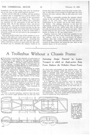
156 Trolleybus Without a Chassis Frame
Page 98
If you've noticed an error in this article please click here to report it so we can fix it.
Interesting Design Patented by London Transport in which an Angle-section Body Frame Replaces the Orthodox Chassis Frame
kN invention concerning the principle of construction of self-propelled road vehicles, but especially applicable o trolleybuses, is the subject of a recent patent specificaion (No. 459,450). The idea, which emanates from the ..ondon Passenger Transport Board, is of particular inerest, as indicating a possible direction in which passenger'chicle developments are likely, to take place.
Presumably, with the object of economizing in weight .nd cost of manufacture without loss of strength and igidity, the scheme is to dispense with a conventional .hassis frame, virtually replacing it by a substantially )nilt main body frame. From the accompanying plan aid elevation drawings the chief features of the design an be understood.
The main longitudinals each comprise two angle-section nemhers, arranged one above the other, and braced and etained at a suitable distance apart by a number of vertial members. At the rear, these are swept over the axles nd, at their extremities, brought together at a point vhence the platform bearers extend. They terminate at he front just behind the front wheels.
Amidships there is a short, similarly constructed backone, from the ends of which diagonals diverge to the side aembers.
To form a forward extension, narrower than the main rame, two further angle members run on each side from
the front main cross-member to the extreme front. The upper ones are straight, whilst the lower are swept upwards to converge with their confreres and to form, in effect, a channel, which carries a full-width transverse member, also of channel section. This arrangement affords great strength to withstand the shock of possible collisions, and,! moreover, is such that the parts liable to be damaged can easily be replaced.
It is suggested that the traction motor be mounted between the central longitudinal and one of the side girders, whilst accessories, battery crates, etc., can be accommodated in corresponding spaces on the other side, or outside the longitudinals.
The floor will generally be supported directly on the upper faces of the upper longitudinals, and on the deep cross-members, which are of dropped construction between the wheel-arches. The body panels will be extended downwards to conceal the body underframe.