


A MECHANICAL ENGINE STARTER.
Page 14
Page 15
If you've noticed an error in this article please click here to report it so we can fix it.
It is quite likely that in the anear future alt motor vehicles will be fitted with engine starters. They may be electrically, mechanically, or otherwise operated. As regards the heavy -brigade, that is to say, those which employ large cylindered engines, say, four-cylinder units of 30 h.p. and upwards, an efficient and reliable electric starter, likely to give prolonged no-trouble secvice notwithstanding the rough usage to which commercial vehicles are frequently subject, does not appear to exist. Unless some unexpected development takes place, the fitting of electrical starters to chassis for loads of upwards of three tons is not yet likely to be general. It is much more probable that an efficient mechanical starter, having very little in its construction which can go wrong even under the roughest treatment.. will have • prior acceptance.
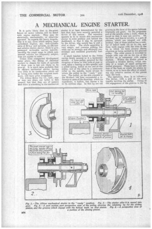
T Albion Motor Car Co., Ltd., may or may not share our belief in this respect, but that they are of opinion that there is something in the mechanical starter is at least demonstrated by the fact that they have recently patented a device of this nature. The intention appears to be to mount this mechanical starter in some position just behind the dashboard, so that it may be operated by the driver, who merely has to pull a cord or chain. The whole apparatus is very simple, and contains nothing but what can be strongly and efficiently constructed and rendered practically foolproof.
A small bracket bolted to the frame carries firmly secured to it a horizontal spindle. A loose pulley, grooved for the reception of three or four coils of rope or cord, takes a bearing on this spindle, and a Foiled spring, bolted at one end to the pulley, and at tire other to a stationary collar on the spindle, tends always to return the pulley to the " ready" position. The pulley, on the side exposed to the flywheel (we here recommend a referenoe to SIMS of the drawings which we reproduce), is hollow, but carries a lip at its extreme edge. In this lip are cut
grooves in the form of the spaces between internally cut gears. On the projecting end of the spindle slides a bush, which is keyed so that it may not revolve. On the bush, and free to revolve, is a pair of pinions, which are integral one with another. One of these pinions has a number of helical teeth cut on its rim, and these teeth engage with the slots in the lip to which we have already drawn attention as being carried by the grooved pulley. The other pinion is intended to engage with cogs cut on the rim of the flywheel as is customary with engine starters. Within the double pinion is arranged a friction device, which consists of a couple of small spring-controlled plungers. These bear on the surface of the bush on which the pinion revolves,.so as to have the effect of retarding any rotative motion of the pinion upon the bush. The operation, then, is as follows;The driver, with a pull on the cord, rapidly revolves the pulley. Owing to the engagement of the grooves in the lip on this pulley with the helical teeth on the pinion, the pulley tries to carry the pinion round with It. The retarding effect of the friction device, however, combined with the helical form of the teeth of the pinion, causes the pulley, with the bush, to slide away from the pinion and towards the flywheel, instead of revolving. It continues to slide until the pinion is in full engagement with the teeth on the flywheel, and at this point a sharouded portion of the pinion comes into contact with the main part of the lip on the pulley, so that further translatory motion is prevented, and the pinion is rapidly revolved, imparting motion to the engine flywheel. Our illustrations*"(reproduced on previous page) show the gear in and out of mesh with the flywheel, and separate details of the helical teeth on the pinion and the grooved lip on the driving pulley.