


A Simple Automatic Brake Adjuster
Page 60
If you've noticed an error in this article please click here to report it so we can fix it.
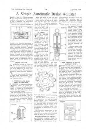
PATENT No. 731,757 shows a means for automatically taking up brake slack due to facing wear; the patentee is H. and T. Industries, Ltd., White Hart Chambers, Launceston, Cornwall.
Applied to a hydraulic expander, as shown in the drawing, one piston is fitted with a tubular extension (I) which encloses an inner extension (2) on the other. The latter has on it a series of turned grooves acting as ratchet teeth.
Attached to the right-hand piston is a split spring-steel sleeve (3) acting as a pawl. When the expansive movement exceeds the pitch of the ratchet teeth, the spring sleeve clicks over a tooth and so creates a new zero position. Another scheme shows a single-piston unit in which the ratchet rod is fixed to the cylinder.
CRANE CONTROL
AVEHICLEcarrying a crane has dual controls arranged so that the crane can be driven from the driver's cab, or the vehicle can be driven from the crane-control seat. This enables one operator to handle the outfit instead of two.
The patent is numbered 725,850, and it comes from Harnischfeger Corp., 4000 West National Avenue, Milwaukee, Wisconsin, U.S.A.
A THERMOSTATIC RICHMIXTURE CONTROL AA SCHEME for aiding cold-weather starting comes in patent No. 730,502, from Solex, Neuilly-sur-Seine, France. It consists of a thermostatic control for the rich-mixture device usually called the "choke."
The operative part of the carburetter is shown in the drawing. The rich mixture has to pass through a port (1) on its way to the intake manifold. The port is square in cross-section and has suspended therein a fiat, U-shaped bimetallic strip (2). When the device is cold, the strip assumes the position shown in which it is well clear of the sides of the square bore, and thus offers little obstruction
to the flow. When the carburetter warms up, however, the forked ends of the strip diverge and close off the bore. This serves to cut down the supply of rich mixture.
A SPRING DAMPING DEVICE
TO prevent spring oscillation is the aim of a damping unit described in patent No. 729,349, by Jonas Woodhead and Sons, Ltd., Kirkstall Road, Leeds, 4. The unit is constructed so that its frictional properties can be easily adjusted to suit a particular spring system.
Referring to the drawing, it will be seen that the device consists primarily of a pair of telescoping tubes, fitted with eyes for attachment to frame and axle. The upper tube is a protection against dirt, whilst the lower one contains a friction piston (1). This comprises three separate shoes faced with friction material consisting of treated wood (2), The three shoes can be adjusted to press against the tube with a selected degree of force. This is adjusted by a central rod (3) which presses on a ball (4). This ball exerts an outward force on three smaller balls (5) which press in • turn upon the wood-faced shoes. The arrangement is duplicated at a lower level (6).
The friction is proportional to the downward force and this can be adjusted by a screwed collar (7) which loads the spring (8) via a cross-pin.
FLEXIBLE COUPLING DESIGN A FLEXIBLE coupling which, in PA. addition to accommodating misalignment also gives a measure of tor
sional resilience, is shown in patent No. 731,814. The patentees are C. Chapman and Compression Ignition, Ltd., The Green, Twickenham, Middlesex.
In the drawing the joint is shown in the position it would assume when trans. milting torque. A threearmed spider (1) is connected with its fellow (2) by three sets of links • (3). These are pivoted in,the-middle at point 4 and when at rest the two arms lie almost in line. When under load, however, they are forced to swing outwards as shown. , All pivot points in the assembly are bushed with rubber, the resiliency of which provides the restoring forces. To increase the range of action of the joint, the links may be made with three separate arms instead of two.
A NEW METHOD OF FIXING GUDGEON PINS PATENT No. 731,327 comes from A. Pitner and S.A. des Roulements a Aiguilles, 133 Boulevard Nationale, Rueil-Malmaison, France. The subject is a means for fixing -a gudgeon-pin in the small end of the connecting rod.
The gudgeon-pin bores and that of the small-end are made to the same size; this is a simple and cheap production method. The gudgeon-pin itself is also made quite parallel and a close fit, but only the end regions are hardened where they fit the bores. The middle portion is left soft, and when the pin has been inserted the centre part is forcibly expanded to form a tight fit in the connecting-rod small end.
Many methods Of expanding are described in the patent, one of which is shown in the drawing. In this case a tapered plug (I) is forced into a corresponding reduced bore in the gudgeon-pin, thus springing it outwards into tight contact.