


A Self-jacking System for a Farm Tractor
Page 54
If you've noticed an error in this article please click here to report it so we can fix it.
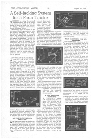
ASCHEME for using the powered implement-lifting gear of a tractor as a means for raising it from the ground, is shown in patent No. 622,261, by Harry Ferguson Incorporated, Detroit. Michigan, U.S.A.
The drawing shows an outline of the well-known Ford-Ferguson tractor with the necessary additions. As is usual, the links (1) are liftable by hydraulic means (not shown) and advantage is taken of this available force to operate the jacking arrangements. A rigid Ushaped frame (2) is provided with an extension (3) which is attached to the lifting arms. The frame is a loose piece, and is merely_ placed with its forked
ends (4) under the axle, and the lifting lieks set in motion. This raises the
rearmost end of the tractor clear of the ground. A chain-connected front frame (5) which is tucked under the crankcase, can he used if a complete lift be required.
A HYDRAULIC GARAGE JACK
AGARAGE jack of the low-lift type, operated by hydraulic
means, forms the subject of patent No. 621,759, which comes from A. Croucher, and Gillett Stephen and Co.. Ltd., both of Atlas Works, Great Book ham, Sutrey.
In the drawing 1 is the lifting member which is carried on' a lowwheeled trolley and pivots about pin 2 -for, its lifting motion. "A parallel-link motion is located under it for ensuring that the load platform always remains horizontal. The arm is raised by a hydraulic cylinder (3) which moves bodily to the right, while its piston remains stationary. The piston contains the operating pump, the ram (4) of which is hand-operated by means of a lever (5). If extra effort be required, this
lever can, by means of a releasable pin, be coupled to the main handle (6). The chief claim made for the design is the ease with which the hydraulic unit can be detached for repair or replacement.
AN ENGINE-CONVERSION MOUNTING
WHEN a petrol engine is replaced by VI' an oil engine, certain problems arise in cdrinection With vibration, it having been found•that the method of mounting'a " siefi engine is' not so effective in the case of an oiler. Such are the views of Sparshatt and Sons (South
/06 ampton), Ltd., Southampton, which concern discloses, in patent No. 622,136, a mounting suitable for such a conversion. 'A point of the scheme is that it is readily adaptabte to variable dimensions of both engine and frame.
The front support remains substantially normal, consisting of some form of rubber block (1) interposed between the engine and the front cross-member. The patent is concerned mainly with the rear support; this comprises a semicircular piece of channel-iron (2) which forms a strong additional cross-member
for the frame. . It is provided with long outside ends which can be cut to length to suit the particular frame. To this cross-member is attached a pair of angle-brackets (3) and these project in a forward direction to meet plates 4 bolted to the sides of the engine. Rubber discs are interposed at the point of meeting, and union effected by bolts (5).
As it has been found that this method of mounting may cause clutch fierceness owing to the pedal reaction shifting the engine slightly, the patent covers also the conversion of the clutch arm from to-and-fro movement to upand-down, the connection with the pedal being by Bowden cable.
A NEW RESILIENT MOUNTING
A VERSATILE rubberPA bushed unit is shown in patent No. •621,638, by A. Hirst and Metalastik, Ltd., both of Eying= Valley Road, Leicester. The device can be used for the mounting of a component such as an engne, or it may even constitute the main suspension system of a vehicle.
The drawing shows the epential features of the device; it consists primarily of a pair of fixed anchorages (1) on the frame, supporting between them a movable platform (2) to which the load is applied. The two units are connected by links (3) held in precompressed rubber bushes at all joints. In action, rising or. falling of the platform is resisted, at first, by shear forces in the rubber, but as the deflection increases, the stress on the rubber becomes compressive owing to the
central platform resisting an increase in its length. Thus the stiffness rate increases with an increase , of load, a desirable feature.
REAR SUSPENSION FOR SIXWHEELERS CONSIDERABLE reduction in ty. re wear during cornering is one of the claims made for an improved design of six-wheeler suspension shown in patent No. 621,449, by V. Prati, Buenos Aires, Argentina. The twin axles of the vehicle are coupled in such a manner that they partake of the steering action as well as the vertical spring movement.
The drawing shows a plan and elevation of a vehicle sprung in the improved manner, and, in broken line, various possible deflections of the rear-most axle. The forward axle is fitted to a leaf-spring in the usual way, but the rear end of the spring is shackled to a rocking lever (1) pivoted on the end of a Nine cross-member (2). The rear end ,of the lever, which carries the trailing aile, is pivoted about a vertical axis (3) so that it can be laterally displaced when cornering, as better shown in the plan view. This motion in no way affects the up-anddown actiOn when road inequalities are encountered, as it shown .in the elevation.
[Owing to Patent Office printing delays, hundreds of patent specifications have, during the paSt six months, been omitted from . the regular sequence. These are now coming through—ED.l