


CONTROL OF PETROL-ELECTRIC VEHICLES.
Page 32
If you've noticed an error in this article please click here to report it so we can fix it.
A Résumé of Recently Published Specifications.
TWO OF THE specifications with which we have to deal this week are concerned with the control and braking —principally the braking—of petrolelectric chassis. Both of them emanate from Tilling-Stevens Motors, Ltd. The first of them, No. 217,989, refers to means whereby an electrical braking effect is obtained by using the motor unit of the transmission as a generator. Separately excited coils are utilized to supply the necessary field for this purpose, and, as a rule, such coils would be additional to the normal series of pails of the machine.
The arrangement is such that, during braking, the series coils are cut out from the armature circuit, and preferably put in series with the separately excited or " braking " coils. A characteristic feature of this invention is that the number of turns available to excite the field is increased when the machine is used for braking. In this way excessive armature current during braking is avoided, since the load is obtainable by means of higher volts and less current than if the ordinary series coils were used alone for excitation during braking. Two constructions embodying the principles of this invention are described and illustrated in the specification. In one the braking coils are excited from the auxiliary generator ; in the other, which is the preferred arrangement, a separate battery is provided for the purpose. Provision is made for closing the throttle of the engine, so as to slow it down before and during braking. In the other specification, No. 217,990 the braking effect is also obtained by using the driving motor as a generator, dissipating the energy in the dynamo armature and other external resistance. The main circuit is broken, thus cutting the dynamo out of the braking circuit, the series coils of the motor are reversed and the motor armature is connected across an external resistance. The reisistance is preferably fixed, and so proportioned as to dissipate the energy generated without any excessive current flowing—so preventing overheating of the dynamo-electric machines. The braking effort may then be altered by varying the field strength of the motor ; where the external resistance is variable, there is no need to vary the strength of the motor.
Other Patents of Interest)
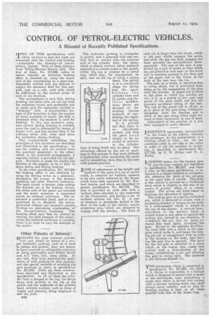
SEALING the joint between cylinder liner and jacket by means of a proper hydraulic packing, such as is used in pumps and presses, does not appear to have occurred to automobile engineers as being practicable until Sidney Smith and A.C. Cars, Ltd., came along. At any rate, they have patented the application of such packing for that purpose, and the special methods of retaining the said packings in place, in specification No. 217,996. There are three constructions described and illustrated in the specification. In all of them the cylinder liner is flanged at the top, the flange being held securely to the top of tae jacket and the underside of the cylinder head, suitable washers, such as those of copper and asbestos, being employed to seal the joint.'
1348 The hydraulic packing is triangular in section, and is disposed with one vertical face in contact with the external wall of the cylinder liner, the other, which is almost vertical, being similarly retained in a conical recess in the jacket, whilst the top is covered by a metal ring, which may for convenience, be split, and on the top of which a spring bears. The spring is of a convenient shape for fitting into the space between the cylinder liner and its jacket, and the three modifications shown are devoted to describing various methods of supporting the upper end of the spring. It . is pointed out that there is
no adjustment needed, and that the parts have simply. to be inserted in position as tha cylinder liner is being fitted into its place. One advantage offered by the use of packings in this manner is that more latitude is permissible when machining the parts and in assembling them than is the case with present practice.
EASE of adjustment of the height and
position of the seats of a car or motor coach, so essential for comfort, appears to be very easily achieved by the means which have been patented by Sir Herbert Austin, and which are described in patent specification No. 217,733. The seat i9 provided at each side with a vertical plate attached to the underside of the framework, and having a set of inclined notches cut into it. A pair of brackets or standards, bolted to the floor of the body of the vehicle, carries projecting pins, which are designed to engage with the notches. The head of each pin is larger than the shank, which is the part which engages the notch, and after the pin has been engaged the head prevents its unintentional disengagement. The rear of the seat is supported by a pair of struts or links which are pin-jointed at each end—at the lower end to brackets secured to the floor and at the upper end to the frame of the back of the seat near the top.
The seat, as a whole, is therefore free to swing about, but is prevented from doing so by the engagement of the pins with the notches. A guard rail is fitted to the plate in which the notches are cut.; it is, as a matter of fact, part and parcel of the plate itself, and this rail prevents accidental tilting of the seat.. The end of the guard rail is off-set, so as to allow of the pins being withdrawn altogether from the bracket., and to allow of the seat being tilted right forward or right backward, in case of need.
Adjustment of the position of a seat thus equipped is easily effected.
INGENIOUS mechanism, incorporated in the frame of the sidecar, whereby the passenger, by the manipulation of a steering wheel or tiller, can tilt the combined outfit to one side or the other in order to aid the machine in cornering, is described in specification No. 217,754, by F. W. Dixon and S. L. Bailey.
LOCKING means for the tipping gear
of gravity-type wagons are described In specification No. 201,917, and there is also, in the same specification, a reference to a simple method of automatic. ally releasing the latch of the tail-gate on the same type of vehicle. The body of the vehicle is pivoted on a horizontal shaft which is slightly to the rear of its centre of gravity when it is evenly loaded. The pivots are knife-edged to facilitate the operation of tipping. The locking gear is a spring-controlled pin, which is designed to couple with a projecting bracket or tongue on the body to a cross-member which is bolted to the top of the Chassis. A vertical lever, convenient to the driver's hand, is rocked across a cam plate to operate the locking pin; moved in one direction, it withdraws the pin, but on being released flies back again, relocking the gear. Moved in the opposite direction, the lever falls into a notch in the cam.plate which holds it, and keeps the locking-pin out of engagement with its hole in the bracket on the body, thus leaving the gear free to operate. The latch for the tail-gate is attached to a chain which, as the wagon tips, comes into contact with a cross-member of the frame, withdrawing a pin and allowing the gate to swing open. The patentee is the Griscom-Russell Co.
THE mechanism which is comprised in specification No. 217,994, for which S. L. Bailey is responsible, is a linkage which is designed to ensure that a brake of the motorcycle type, embodying a single shoe which is moved into contact with a circular rotating brake rim, shall always move radially, and so that its braking surface is kept at all times parallel with that Of the brake ring.