


Power-operated Steering Gear
Page 72
If you've noticed an error in this article please click here to report it so we can fix it.
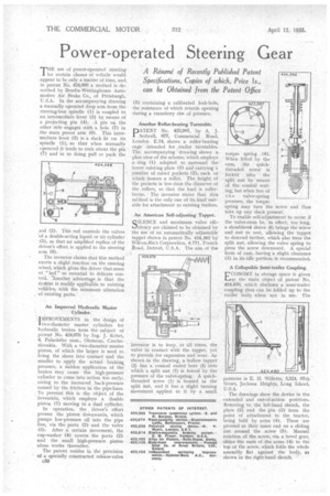
THE use of power-operated steering. for certain classes of vehicle would .appear to be only a matter of time, and in patent No. 424,668 a method is described by Bent:lix-Westinghouse Automotive Air Brake Co., of Pittsburgh, U.S.A. In the accompanying drawing a manually operated drop arm from the steering-box spindle (1) is coupled to an intermediate lever (3) by means of a projecting pin (4). A pin on the other sideengages with a hole (7) in the main power arm (6). This inter' mediate lever (3) is a slack fit on its . spindle (1), so thht when manually
perated it tends to rock about the pin (7) and in so doing pull or push the rod (2). This rod controls the valves of a double-acting liquid or air cylinder .(5), so that an amplified replica of the driver's effort is applied to the steering arm (6).
The inventor claims that this method exerts a slight reaction on the steering wheel, which gives the driver that sense of "feel" so essential to delicate control. *Another advantage is that the system is readily applicable to existing vehicles, with the minimum alteration , of existing parts.
An Improved Hydraulic Master Cylinder.
IMPROVEMENTS in the design of two-diameter master cylinders for hydraulic brakes form the subject of patent No. 424,676 by Ing. J. Kebrt, 4, Palackeho nam., Olomouc, Czechoslovakia. With a two-diameter master piston, of which the larger is used to bring the shoes into contact and the smaller to apply the actual braking pressure, a sudden application of the brakes may cause the high-pressure cylinder to come into action too early, .owing to the increased back-pressure caused by the friction in the pipe lines. To prevent this is the object of the invention, which employs a double piston (1) moving in a dual cylinder.
In operation, the . driver's effort presses the piston downwards, which pumps low-pressure oil into the pipe line, via the ports (2) and the valve (3). After a certain movement, the cup-washer (4) covers the ports (2) and the small high-pressure piston alone works thereafter.
The patent resides in the provision of a specially constructed release-valve c50 (5) containing a calibrated leak-hole, the resistance of which retards opening during a transitory rise of pressure.
Another Roller-bearing Turntable.
PATENT No. 423,987, by A. J. Sedwell, 677, Commercial Road, London. E.14, shows a roller-bearing cage intended for trailer turntables. The accompanying drawing shows a plan view of the scheme, which employs a ring (1) adapted to surround the lower existing plate (3) and carrying a number of raised pockets (2), each of whicii houses a roller. The height of the pockets is less than the diameter of the rollers, so that the load• is rollerborne. The inventor states that this mkhod is the only one of its kind suitable for attachment to existing trailers.
An American Self-adjusting Tappet.
SILENCE and maximum valve efficiency are claimed to be obtained by the use of an automatically adjustable tappet shown in patent No. 424,362 by Wilcox?Rich Corporation, 9,771, French Road, Detroit, U.S.A. The aim of the
inventor is to keep, at all times, the valve in contact with the tappet, yet to provide for expansion and wear. As shown in the drawing, a hollow tappet (2) has a conical ended bore (5) into which a split nut (7) is forced by the pressure of the valve-spring. A quickthreaded screw (1) is housed in the split nut, and it has a slight turning movement applied to it by a small torque spring (4). When lifted by the cam, the quickthreaded screw is locked irito the split nut by means of the conical seating, but when free of t h e valve-spring pressure, the torque spring may turn the screw and thus take up any slack present.
To enable self-adjustment to occur if the valve-stem be, in effect, too long, a shouldered sleeve (6) brings the screw and nut to rest, allowing the tappet to descend farther, which also frees the split nut, allowing the valve spring to press the screw downward, A special form of cam, having a slight clearance (3) in its idle portion, is recommended.
A Collapsible Semi-trailer Coupling.
ECONOMY in storage space is given as the main object of patent No. 424,450, which discloses a semi-trailer coupling that can be folded up to the trailer body when not in use. The
patentee is E. H. Willetts, 3,524, 87th Street, Jackson Heights, Long Island, U.S.A.
The drawings show the device in the .extended and out-of-action positions. Referring to the left-hand sketch, the plate (2) and the pin (3) form the point of attachment to the tractor, being held by arms (4). These are pivoted at their inner end on a sliding nut around the screw (5). Manual rotation of the screw, via a bevel gear, slides the ends of the arms (4) to the top of the screw, which folds the whole assembly flat against the body, as shown in the right-hand sketch.