


Dual Wheels with Independent Movement
Page 66
If you've noticed an error in this article please click here to report it so we can fix it.
A Resume of Recently Published Patera Specifications THEmethod of mounting wheels for dual tyres, which is shown in patent No. 368,588, by S. F. Higbee 481, Beaufait Avenue, Detroit, U.S.4and S. A. Griggs, 150, Argyle Road, Walkerville, Ontario, is of interest owing to certain points which the specifications raise in connection with the use of dual tyres.
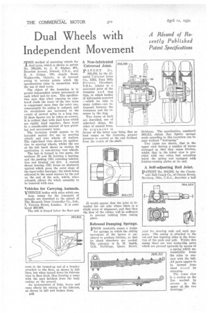
The object of the invention is to permit independent rotary movement of each wheel and its tyre. The specification says that when running on cambered roads the inner of the two tyres is compressed more than the outer one, consequently its radius is reduced, and its revolutions are increased to the extent of several miles in a long run. If these figures can be taken as correct, it is evident that with dual tyres which are rigidly fixed together, there must be a considerable amount of tyre grinding and unnecessary wear. The invention would appear to be intended mainly for use on steering wheels and rear wheels of trailers. The right-hand view shows ita application to steering wheels, whilst the one at the left hand shows in section its application to non-driving rear wheels.
The hub is formed in two parts, the surfaces 20 and 24 forming a bearing,
and the (30) retaining lubrication and keeping out dirt. A central thrust bearing (32) forms an abutment against which press the outer rings of the taper-roller bearings ; the whole being adjusted in the usual manner by the nut on the end of the axle, which, when released, allows the whole assembly to be removed with ease.
Vehicles for Carrying Animals.
VEHICLE bodies -with sides which can form ramps for the transport of animals are described in the patent of The Monarch Door Controller Co., Ltd., 7, Victoria Street, London. It is numbered 367,805.
The side is hinged below the floor and rests in the turned-up end of a bracket attached to the floor, as shown in full lines, but when turned down its fulcrum rises to floor level, thus forming a ramp with the part farthest from the body resting on the ground.
An arrangement of links, levers and cams effects the raising of the fulcrum, as shown in full and broken lines.
B48
A Non-lubricated Universal Joint.
PATENT No. 368,456, by the Almetal Universal Joint Co., 1553, East 55th Stree t, Cleveland, U.S.A., relates to a universal joint of the trunnion a n d ring type, in which bushes of deformable material —which we take to mean rubber—are interposed between the trunnions and the recesses in the ring.
Two forms of bush are described, one of spherical shape, the other of conical form, the argument in favour of the latter type being that as load comes on the trunnion, greater pressure is exerted at the end farthest from the centre of the shaft.
it would appear that the joint is intended for use only where there is a slight error of alignment, and that then the flow of the rubber will be sufficient to prevent rubbing from taking place.
Rebound Damping Springs.
FROM Australia comes a design for springs in which the sliding movement of the leaves is employed to produce friction, so that no shock absorbers are needed. The patentee is R. H. Smith, O.K. Buildings, Queen Street, Brisbane. The specification, numbered 368,313, claims that lighter springs made according to this invention can be used without "bottoming."
Two types are shown, that in the upper view having a number of leaves arranged so that they cause friction, whilst that in the lower view is provided with one extra leaf extending below the spring and equipped with friction-causing plates at its end.
A Self-adjusting Ball Joint.
PATENT No. 364,203, by the Cincinnati Ball Crank Co., of Disney Street, Marburg, Ohio, U.S.A., describes a ball joint for steering rods and such purposes. The casing is attached to the rod and has tapering sides in the direction of the push and pull. Within this easing there are two wedge-like pats which are pressed upwards by means of a spring which automatically keeps the sides in contact with the balk All parts appear to be formed from sheet steel by stamping. 308,313 The lower view Is a section on the line marked by arrows in the upper of the two drawings.