


A Novel Fuel Pump
Page 52
Page 53
If you've noticed an error in this article please click here to report it so we can fix it.
A New Design Known as the En, which has Given Good Results in Tests Made with a Junkers Sin gle-cylindered Two-stroke Engine
AT the headquarters of the Vortex Silencer Co., Ltd., in the grounds of the old Wembley Exhibition, work is being carried out upon the development of a new type of fuel pump, known as the MEL, which is of a particularly interesting design.
From our own observations made during a trial of this fuel pump on a Junkers single-cylindered engine of the opposed-piston type, running on the two-stroke cycle and having a bore and stroke of 65 mm. and 210 min. resneclively, and from the report of a test carried out with the same engine by Dr. S. J. Davies, PL.D., M.Sc., M.I.Mech.E., we have formed the opinion I hat the E.H. pump shows a distinct advance, and that its performance may be considered highly satisfactory.
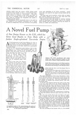
It will be seen from the diagrammatic drawing of the pump in section that there are two main moving parts —the plunger and the sleeve ; each is eccentric driven—the plunger from a single eccentric and the sleeve from a pair of eccentrics set on each side of and at an angle of 180 degrees to the plunger eccentric. The eccentric rods are coupled to cross-heads (not shown in the drawing), which work in guides, whilst both the sleeve and the plunger float in the cross-heads.
Surrounding the upper part of the sleeve is a second sleeve, or "muff," that can be raised or lowered by the control on the left, and this regulates the period of flow of fuel and the quantity discharged.
The upper compartment of the pump body forms a reservoir for the fuel, which, of course, is free to flow into or out of the ports in the sleeve, the discharge being through the fixed plunger to the pipe line. The ports, incidentally, consist actually of internal and external grooves with communicating holes.
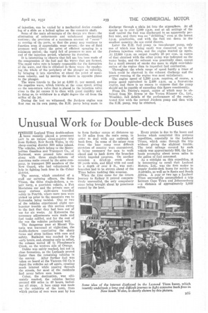
At the left of the diagram showing the action of the pump is seen the pump full of oil, the plunger beginning its upward stroke and the sleeve starting to move downwards. Just before mid-stroke, when the relative velocity of the sleeve to the plunger is approaching its maximum, the lower ports close and the impulse produces a wave in the oil which travels without impedence to the non-return valve at the jet and thence to the jet itself.
The second diagram shows the commencement of delivery, and this will continue until the upper ports pass below the muff.
The valve rate of this port is also very high, as the periphery is greater than in the first case, and the sudden release of pressure at the base of the column of compressed fuel causes a negative wave to travel upwards to the jet.
Should the release port open immediately after the bypass port is closed, the positive wave will still travel to the jet, to be followed almost instantaneously by the negative wave, and, therefore, the actual duration of the injection period can be reduced to a degree or so-of crankshaft movement, without curtailing the initial pressure at the jet, the time required to build up this pressure or the angular period of the fall to zero.
The time of closing of the by-pass valve, i.e., the moment
of injection, can be varied by a mechanical device consisting of a slide on a helical spline on the eccentric shaft.
Some of the main advantages of the design are these : the elimination of unharmonic and unbalanced mechanical motions ; the provision of a maximum amount of " cover " or overlap of the ports, so that the pump may continue to function even if appreciable wear occurs ; the use of fluid pressure well above the point of efficient spraying in a minimum period; the rapid fall of pressure to zero at the end of the injection period, whatever its duration.
It is interesting to observe that full use has been made of the compression of the fuel and the waves that are formed. The rapid valve rate is largely responsible for the formation of the wave, and this is obtained in three ways—by employing the whole of the periphery of the plunger as valve-lip, by bringing it into operation at about the point of maximum velocity, and by moving the sleeve in opposite phase to the plunger.
The wave travels to the jet at 4,000 ft. per second, and the negative wave, which travels at the same speed, acting on the non-return valve that is placed in the injection valve close to the jet causes it to close with great rapidity and, in doing so, to withdraw to a slight degree the oil from the orifice of the jet.
During the test we witnessed, the Junkers engine was first run on its own pump, the E.H. pump being made to discharge through a plain jet into the atmosphere. At all speeds up to over 1,000 r.p.m. and at all settings of the muff control the fuel was discharged in an apparently perfect mist, and there was no "dribbling," even at the lowest r.p.m. practicable, and with the fuel cut down to the smallest quantity the eye could discern.
Later the E.H. fuel pump (a two-plunger pump, only one of which was being used) was connected up to the Junkers iujeetion valve, and the engine started up again. At 12,000 r.p.m. an output roughly 25 per cent. in excess of that obtained with the other pump was indicated on the water brake, and the exhaust was practically clear, except for a small amount of smoke due more to slight over-lubrication of the engine than to imperfect fuel combustion.
Throughout the whole range of speed hardly a trace of black could be observed in the exhaust discharge and the general running of the engine was most satisfactory.
The engine speed of 1,200 r.p.m. requires, of course, a pump speed equivalent to 2,400 r.p.m. on a four-stroke engine, and there is no reason to suppose that the pump should not be capable of exceeding this figure considerably.
From Dr. Davies's report, copies of which may be obtained from Mr. Evans at the Vortex Silencer Co,, Ltd., Wembley, full details of the performance of the engine, tested first with the normal Junkers pump and then with the E.H. pump, may be obtained. _