


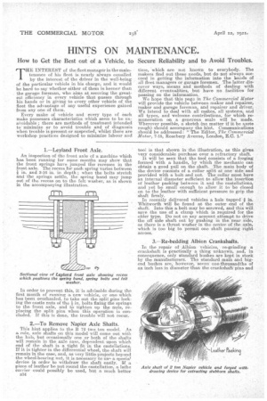
1.—Leyland Front Axle.
Page 30
Page 31
If you've noticed an error in this article please click here to report it so we can fix it.
An inspection of the front axle of a machine which Las been running for some months may show that the front springs have jumped the recesses in the front axle.. The recess for each spring varies between if in. and 3-16 in. in depth ; when the bolts stretch and the springs settle, the spring band may jump out of the recess, on to the felt washer, as is shown in the accompanying illustration.
In order to prevent this, it is a,dvisable. during the first month of running a new vehicle, or one which has been overhauled, to take out the split pins lock-, ing the castle nuts of the in. bolts fixing the springs to the front axle, and to tighten up the nuts, replacing the split pins when this operation is concluded. If this is done, the trouble will not recur.
2.—To Remove Napier Axle Shafts.
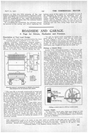
This hint applies to the B 72 two ton model. As a rule, axle shafts on this model will come out with the hub, but occasionally one or bath of the shafts will remain in the axle case, dependent upon which end of the shaft is a tight fit in the castellations. If it is tighter in the differential wheel, the shaft will remain in the ease, and, as very little projects beyond the wheel-bearing nut, it is necessary to use. a special device in order to withdraw the shaft easily. If a piece of leather be put round the eastellation, a lathe eairier could possibly be used, but a much better 534
tool is that shown inthe illu.stration, as this gives very considerable purchase over a refractory shaft.
It will be seen that the tool consists of a forging formed' with a, handle, by which the: mechanic can obtaina good pull on the shaft. The main body of the device consists of a collar split at one side and provided with a bolt and nut. The collar must have an internal 'diameter sufficient to allow the insertion of leather packing between it and the eastellations, and yet he small enough to allow it to be closed on to the leather with sufficient pressure to grip the shaft firmly. In recently delivered vehicles a hole tapped -ain. Whitworth will be found at the outer end of the shaft. Into this a. bolt may be screwed, and' thiswill save the usev of a clamp which is required for the older type. Do not on any account attempt to drive the aff side shaft out by pushing in the near Side, as there is a thrust washer in the centre of the axle, which is too big to permit one shaft passing right across.
3.—Re-bedding Albion Crankshafts.
In the repair of Albion vehicles, re-grinding a crankshaft is practically a thing unknown, and, in consequence, only standard bushes are kept in stock by the manufacturers. The standard main and bigend bushes are, however, seven one-thousandths of an inch less in diameter than the crankshaft'pins and
journals, so that very little scraping of the new bushes is required to accommodate a standard crankshaft, and, if for any reason it is found necessary to grind the crankshaft to; say, eight one-thousandths of an inch below standard, then the ordinary bushes would be quite suitable.
In re-bedding the crankshaft, the cylinders should be screwed to the easing, and before replacing the
bottom cover of the engine it is advisable to test if the lubricator is working, by operating same by hand. Oil should be put into the lubricator, the engine turned until the pistons are about half stroke, and by looking from the rear end of the engine, if everything is in order, oil will be observed dripping into the four oiling rings from the main bearings.