


Auxiliary brakes worth a second thought
Page 31
Page 32
If you've noticed an error in this article please click here to report it so we can fix it.
If vehicle weights are eventually increased, the case for auxiliary brakes will be a strong one argues H. W. F. Davidsqn. They have many technical advantages, not least that they minimise the strain on drums and linings, and they would be welcomed by the road safety lobby WHILE our Government continues to procrasinate over the increase in gross vehicle weights, the time is ripe for vehicle engineers to reconsider certain aspects of the engineering requirements of heavier vehicles and in particular auxiliary braking equipment.
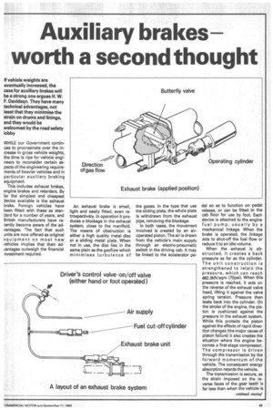
This includes exhaust brakes, engine brakes and retarders. By far the simplest and cheapest device available is the exhaust brake. Foreign vehicles have been fitted with these as standard for a number of years, and British manufacturers have reently become aware of the advantages. The fact that such units are now offered as original quipment on most new vehicles implies that their advantages outweigh the financial nvestment required. An exhaust brake is small, light and easily fitted, even retrospectively. In operation it produces a blockage in the exhaust system, close to the manifold. The means of obstruction is either a high quality metal disc or a sliding metal plate. When not in use, the disc lies in the same plain as the gasflow which minimises turbulence of the gases. In the type that use the sliding plate, the whole plate is withdrawn from the exhaust pipe, removing the blockage.
In both rases, the movement involved is created by an airoperated piston. The air is drawn from the vehicle's main supply through an electro-pneumatic switch in the driving cab. It may be linked to the accelerator pe dal so as to function on pedal release, or can be fitted to the cab floor for use by foot. Each device is attached to the engine fuel pump, usually by a mechanical linkage. When the brake is operated, the linkage acts to shut-off the fuel flow or reduce it to an idle volume.
When the exhaust is obstructed, it creates a back pressure as far as the cylinder. The unit construction is strengthened to retain the pressure, which can reach 482.3kN/sqm (70psi). When this pressure is reached, it acts on the reverse of the exhaust valve head, lifting it against the valve spring tension. Pressure then leaks back into the cylinder. On the stroke of the engine, the piston is cushioned against the pressure in the exhaust system. While this protects the piston against the effects of rapid direction changes (the major cause of piston failure) it also creates the situation where the engine becomes a first-stage compressor. The cornpressor is driven through the transmission by the forward momentum of the vehicle. The consequent energy absorption retards the vehicle.
The transmission is secure, as the strain imposed on the reverse faces of the gear teeth is far less than when the vehicle is used in reverse gear. The cost of this retardation is about £300, plus fitting time of half a day.
An exhaust brake of this type is not suitable for two-stroke engines. For these and those of the Cummins range, C. L. Cummins assisted in the design of an engine brake, the best known of which is the Jake Brake. It consists of a device mounted on top of the cylinder head which hydraulically bears on top of the exhaust valve. This unit effectively alters the valve timing. As the piston completes the compression stroke, with maximum pressure achieved at top dead centre, the compressed gases are vented to the exhaust by the device opening the exhaust valve. The energy used to create this compression and the energy necessary to return the piston to the bottom of the stroke, as no combustion has taken place, is drawn from the vehicle's momentum, which in turn creates the retardation. The net result in both the exhaust and engine brake is to slow the vehicle by using energy in the form of the vehicle's forward movement. The maximum effect of an exhaust brake is obtained when the vehicle is fittted with high tension exhaust valve springs. With the engine brake, maximum effect is when engine revolutions and swept volumes are high.
Although the investment cost of an exhaust brake at £300 is only one per cent of vehicle cost, the probable returns on brake and tyre life easily off-set the additional cost. The engine brake is more complex and therefore more expensive, at about £800, plus a day fitting {not applicable if factory fitted). The rate of retardation is, however, much greater.
For comparison, using a Cummins NTE 290 engine, the maximum retarding horsepower at the flywheel for each would be: Exhaust brake developing 65psi 225hp.
Engine brake at maximum setting 393hp.
These figures may mean little to an uninformed member of the transport staff, but the effects can be illustrated by using the total power absorption in the following equation to show the angle of gradient that a vehicle, of given weight, is capable of descending without recourse to the foundation brakes.
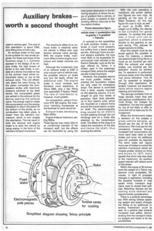
Power absorption figure vehicle mass x acceleration due to gravity x % gradient = Velocity In contrast to the capabilities of both auxiliary brakes, a retarder is much more powerful but suffers from a heavy weight penalty. Although there are several designs available, the type most likely to be acceptable for commercial road vehicles is the Electric Retarder, such as the design offered by Telma. it is widely used in the passenger transport field, where the weight penalty is less important.
However, the possible returns are much greater. Indeed, in practice the foundation brakes are only used for emergency stops. The device is controlled from a lever, usually mounted op the steering column. It is arranged to give four levels of operation. Each level operates up to four electric coils, which are mounted on a secure frame around the transmission propellor shaft The electromagnetic drag caused by an electric current passing through the coil windings acts on a metal disc attached to the transmission shaft. The effect of the drag is to retard the revolution of the disc and hence the shaft, thus slowing the vehicle.
With the unit operating a maximum, the power absorp tion figures are very high, de pending on the type of uni fitted. However, for this high figure the cost is high as well as much as £2,000. With •i weight up to 330kg, the retarde is not suitable for good: vehicles. To combat this prob lem, a focal unit can bE specified, which is attache( directly to the gearbox or rea axle casing. This reduces thf weight penalty to 232kg.
Even this weight must be bal anced against the possible re turns. For instance, a retarde can extend brake lining life by a: much as six hundred per cent With the exhaust and engin4 brakes, one hundred per cen extension should be achieve. ble. To operators in particular!) tortuous areas, even the retarde may prove attractive. Tyre lifi can be expected to lengther through their application. Re larders, however, are expensivi items which require regula cleaning and lubrication.
The savings available from al these devices mean they war rant serious consideration. As it most things, the cheaper the installation, the less the capabil. ity, but all are likely to offer re. turns that will at least pay for the investment.
When the Government make; .a decision on the subject 01 gross vehicle weights, we should see the day of the 40. tonne lorry. We must pay for this concession, however, througi. increased fuel consumption anc more rapid wear rates on bott brakes and tyres. An additiona axle will probably be required The extra loads will require more use of brakes to control the vehicle's momentum which wili impose greater strains on lining and drums (in 1977, Volvc agreed that drum size was close to the maximum). An auxiliary speed retarder will relieve some of this stress.
Within the scope of 40 tonnes, even the weight of a Telma may become more acceptable. Obviously, in light of proposed changes in legislation, including the possible increase in road speed limits, transport engineers need to review their policies. Retarding devices are becoming more relevant and require further consideration.
There is a political advantage, too. With strong lobbies opposing weight and speed changes, the fitting of an additional retarding mechanism could be seen as a postive step towards increased road safety, demonstrating that the transport industry accepts and reacts to its responsibilities.