 1
1 2
2 3
3 4
4 5
5 6
6 7
7 8
8 9
9 10
10 11
11 12
12 13
13 14
14 15
15 16
16 17
17 18
18 19
19 20
20 21
21 22
22 23
23 24
24 25
25 26
26 27
27 28
28 29
29 30
30 31
31 32
32 33
33 34
34 35
35 36
36 37
37 38
38 39
39 40
40 41
41 42
42 43
43 44
44 45
45 46
46 47
47 48
48 49
49 50
50 51
51 52
52 53
53 54
54 55
55 56
56 57
57 58
58 59
59 60
60 61
61 62
62 63
63 64
64 65
65 66
66 67
67 68
68 69
69 70
70 71
71 72
72 73
73 74
74 75
75 76
76 77
77 78
78 79
79 80
80 81
81 82
82 83
83 84
84 85
85 86
86 87
87 88
88 89
89 90
90 91
91 92
92 93
93 94
94 95
95 96
96 97
97 98
98 99
99 100
100 101
101 102
102 103
103 104
104 105
105 106
106 107
107 108
108 109
109 110
110 111
111 112
112 113
113 114
114 115
115 116
116 117
117 118
118 119
119 120
120 121
121 122
122 123
123 124
124 125
125 126
126 127
127 128
128 129
129 130
130 131
131 132
132 133
133 134
134 135
135 136
136 137
137 138
138 139
139 140
140 141
141 142
142 143
143 144
144 145
145 146
146 147
147 148
148 149
149 150
150 151
151 152
152 153
153 154
154 155
155 156
156 Rotary Injection Pump
Page 116
If you've noticed an error in this article please click here to report it so we can fix it.
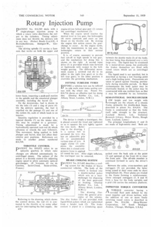
PD.ATENT No. 814,589 deals with a I single-plunger injection pump in which a rotary valve distributes the output to the cylinders. Timing adjustment does not throttle the delivery side in any way. (Robert Bosch G.m.b.H., 4 Breitscheidstrasse, Stuttgart-W., Germany.) The driving spindle (1) carries a facecam that works on both the upper and lower faces, imparting a push-pull motion to the spindle and the associated plunger assembly, including the barrel (2).
On the downstroke, fuel is drawn in via the inlet (3) and a ring of ports (4). On the delivery upstroke, the fuel is expelled via the passage (5) and one of the outlets (6), each of which leads to an injector.
Quantity regulation is provided by a tapered throttle (7) on the intake side; this may be coupled to a governor. Timing adjustment is made by a hydraulically operated rack-rod (8) which advances or retards the cam followers. This movement, being applied to both plunger and barrel, does not affect their relative port positions. References are made to another patent numbered 814,709.
THROTTLE CONTROL DATENT No. 813,872 refers to an epicyclic gearbox in which ratio changes are effected automatically by centrifugal means. The subject of the patent is a throttle control for adjusting engine speed to allow automatic upward gearchanges. (P. Voreaux, 42 rue de Garches, Saint-Cloud, Seine-et-Oise, France.)
Referring to the drawing, which shows the control device, the rod (1) is connected to the throttle or to some other unit for interrupting the fuel supply. An B26 engine-driven helical gear-pair (2) rotates the centrifugal mechanism (3).
When the engine speed reaches the desired level in low gear, the bobweights (4) move outwards and exert an end thrust on the throttle rod. By slowing the engine this action causes the gearchange to occur. As the engine slows, with the transmission in top gear, the bobweights return to their normal position.
It is, of course, necessary to prevent fuel cut-off at high speeds in top gear, and the mechanism for doing this is shown on the right. A second input drive (5) is provided which runs forward or backwards with respect to the bobweight gearing. The differential movement causes a screwed rod (6) to lie either to the right (low gear) or to the left (top gear); in the latter position it overrides the governing mechanism.
FITTING TUBELESS TYRES
BEFORE a tubeless tyre can be inflated its side walls must make sealing contact with the wheel rim. Patent No. 814,716 shows an effective tool for doing this. (Dunlop Rubber Co., Ltd., 1 Albany Street, London, N.W.1.)
The device is simply a tourniquet; this is placed around the tread and tightened so as to squeeze the tyre tightly against the rims walls. Referring to the drawing, 1 is a canvas belt to surround the tyre; this has an adjustable grip (2) to accommodate various sizes of tyre. A toggle clamp (3) completes the assembly; when this is closed compressive force is applied all round the tyre. After slight inflation, the tourniquet can be removed.
BRAKE COOLING SYSTEM
DATENT No. 813,442 describes a cool
ing system for the brakes of heavy commercial vehicles. The body of the vehicle is formed into a double-walled jacket which acts as a heatoxchanger for disposing of the heat generated by braking. (Dunlop Rubber Co., Ltd., 1 Albany Street, London, N.W.I.) The drawing illustrates the general principles of the scheme. The disc brakes (1) are provided with liquid-filled jackets which are replenished from a header tank (2). The brake coolant is piped to a circulating space between the double walls (3) of the body, the heat being thus dissipated over a very large area. The liquid may be circulated by a motor-driven pump, but preferably the brakes themselves are fitted with vaned rotors which act as centrifugal pumps.
The liquid used is not specified, but is described as having a low freezing point and a high boiling point. Precautions are taken to guard against freezing, particularly during immobile periods. In these circumstances the body jacket may be electrically heated, or the jacket may be constructed with one resilient face, so that it may be extended by ice formation.
SEMI-INTEGRAL DOUBLE-DECKER I OW height and low weight with 1—■ strength are the objects of a chassis frame, primarily for double-deck buses, described in patent No. 814,414. The frame is constructed so that the body itself adds strength to the structure. (Leyland Motors, Ltd., Technical Research Library, Motor Works, Hough Lane, Leyland, Lancs.)
The principal longitudinals (1 and 2) are made of high-tensile steel. Both are arched over the back axle at the point (3) and upswept at the front (4) to clear the front axle. The off-side member is continued forward to carry the driver's cab.
Between the axles, cross-members and outriggers (5) are provided, the latter being joined at their outer ends by short longitudinals (6). Floor plates are riveted to the frame forming a reinforcement. Three enlarged outriggers (7, 8 and 9) form a base for the body uprights and a grid (10) carries the entrance platform.
IMPROVED TORQUE CONVERTER
rAA TORQUE converter having a toroidal fluid path defined by the usual impeller and driven turbine, with the addition of one or more freely revolving vaned rotors is described in patent No. 814,206. (Borg-Warner Corporation, 310 South Michigan Avenue, Chicago, Michigan, U.S.A.)