


An AEC, Vacuum Brake for oilers
Page 52
If you've noticed an error in this article please click here to report it so we can fix it.
A Resume of Recently Published Patent Specifications
WHILST in a spark-ignited engine VV there is an ample supply of subLiOrmal pressure for brake operation, the .advent of the oiler has brought with it the necessity of a special brake exhauster. To avoid the need for this expensive unit is the object of the scheme shown in patent No. .451,424 by G. J, Rackham, W. S. Dack, and the Associated Equipment Co„ Ltd., of Southall, Middlesex. This system employs a throttle-valve (1) in the air-intake pipe of the-engine. During normal running . this is fully open and, therefore, ineffective, and is closed only when the brakes are applied: being connected to the pedal by means of a linkage (2, 3, and.4) the bell-crank (3) giving a magnified movement so that the valve is fully closed at the beginning of the pedal stroke. The resultant suction is conveyed to the servo system, via a ball valve (5) in the engine intake; this valve also passes sufficient air to enable the engine to run at an idling speed.
Increasing the Durability of Tappets.
AMETHOD of fixing a hard face on to a soft tappet body forms the _subject of patent No. 450,486, by Wilcox-Rich Corp„ 9771, French Road, Detroit, Mich., -U.S.A. The method de450.466 scribed" employs elec tric welding as the banding medium, and the drawing shows the assembly before welding. The tappet body (5) has an upper flange (3) which is bevelled on its top face. A hard steel disc (2) is placed on the top and the whole mounted between ehatrodes (1 and 4). When current is applied, the thin bevelled edge is first heated, and, as the pieces unite under pressure, the line of weld travels outwards until the whole faces are united. The assembly is then placed in a die and subjected to a forging operation which further strengthens -the joint
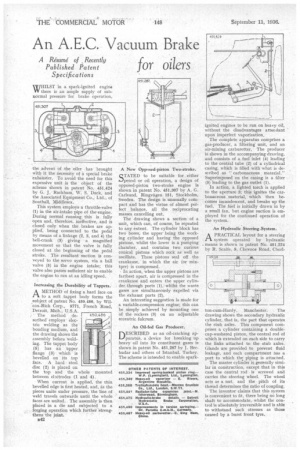
A New Opposed-piston Two.stroke.
STATED to be suitable . for either petrol or oil operation, a design of opposed-piston two-stroke engine is shown in patent No. 451,307 by A. G. Carlsund, Ringyagen 151, Stockholm, Sweden. The design is unusually compact and has the virtue of almost perfect balance, all the reciprocating masses cancelling out. The drawing shows a section •of a unit, which can, of course, be repeated to any extent. The cylinder block has two bores, the upper • being the working cylinder and having the opposed pistons, whilst the lower is a pumping chamber, and contains two curious conical pistons which rock as well as oscillate. These pistons seal off the crankcase, in which the air (or mixtpre) is compressed. • In action, when the upper pistons are farthest apart, air is compressed in the crankcase and enters the upper cylinder through ports (1), whilst the waste gases are simultaneously expelled via the exhaust ports (2). An interesting suggestion is made for a variable-compression engine; this can be simply achieved by mounting one of the rockers (3) on an adjustable eccentric fulcrum.
An Oil-fed Gas Producer.
DESCRIBED as an oil-cracking apparatus, a device for breaking up heavy oil into its constituent gases is shown in patent No. 451,287 by T. Ben. hudar and others of Istanbul, Turkey. The scheme is intended to enable spark ignited engines to be run on heavy oil, without the disadvantages attendant upon imperfect vaporization. The complete apparatus comprises a gas-producer, a filtering unit, and an air-mixing carburetter. The producer is shown in the accompanying drawing, and consists of a fuel inlet (4) leading to the central tube (2) al a cylindrical casing, which is filled with what is described as " carbonaceous material." Superimposed on the casing is a filter (5) leading to the gas outlet (1). In action, a lighted torch is applied to the aperture 3; this ignites the carbonaceous material, which then becomes incandescent, and breaks up the fuel. The fuel is initially drawn in by a small fan, but engine suction is employed for the continued operation of the system.
An Hydraulic Steering-System.
A PRACTICAL layout for a steering .1-% system operated by hydraulic . means is shown in patent No. 451,224 by R. Scaife, 8, Clarence Road, Chorl ton-cum-Hardy, Manchester. . The drawing shows the secondary hydraulic cylinder, that is, the part that operates the stub axles. This component comprises a cylinder containing a doublecup-washered piston, the central rod of which is extended on each side to carry the links attached to the stub axles, Glands are provided to, prevent fluid leakage, and each compartment has a port to which the piping is attached. The master cylinder is generally similar in construction, except that in this case the central rod is screwed and carries the steering wheel. The wheel acts as a nut, and the pitch of its thread, determines the ratio of coupling. The inventor claims that this system is convenient to fit, there being no long shaft to accommodate, whilst the control is absolutely irreversible and is able to withstand such stresses as those caused by a burst front tyre.