


English Maker Supplies
Page 40
Page 41
If you've noticed an error in this article please click here to report it so we can fix it.
Canada's First Trolleybuses
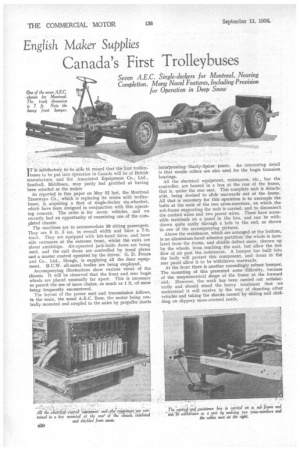
Seven A.E.C. Single-deckers for Montreal, Nearing Completion. Many Novel Features, Including Provision for Operation in Deep Snow
IT is salisfactorY to:be.able tO record that the first trolley buses to be put into operation in Canada will be of British manufacture, and the Associated Equipment Co., Ltd., Southall, Middlesex, may justly feel gratified at having been selected as the maker
As reported in this paper on May 22 last, the Montreal Tramways CO., which is replacing its trams with trolley. buses, is, acquiring a fleet of single-decker six-wheelers, which have been designed in conjunction with this operating concern. The order is for seven vehicles, and we recently had an opportunity of examining one of the completed chassis.
The machines are to accommodate 38 sitting passengers. They are 8 ft. 3 ins, in overall width and have a 7-ft. track. They are equipped with left-hand drive, and have side entrances at the extreme front, whilst the exits are about amidships. Air-operated jack-knife doors are being used, and the exit doors are controlled by tread plates and a master control operated by the driver. G. D. Peters and Co., Ltd., Slough, is supplying all the door equipment. M.C.W. all-metal bodies are being employed.
Accompanying illustrations show various views of the chassis. It will be observed that the front and rear bogie wheels are placed unusually far apart. This is necessary tcr permit the use of snow chains, as much as 1 ft.. of snow .being frequently encountered.
The layout of the power unit and transmission follows, in the main, the usual A.E.C. lines, the motor being centrally. mounted and coupled to the axles by propeller shafts incorporating -Hardy-Spicer joints. An interesting detail is that needle rollers are also used for the bogie trunnion bearings.
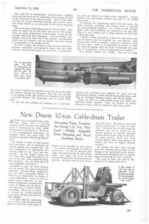
All the electrical equipment, resistances, etc., bar the controller, are housed in a box at the rear of the frame, that is, under the rear seat. This complete unit is detachable, being devised to slide rearwards out of the frame. All that is necessary for this operation is to uncouple the bolts at the ends of the two cross-members, on which the sub-frame supporting the unit is carried, and to disconnect the control wires and two power wires. These have accessible terminals on a panel in the box, and can be withdrawn quite easily through a hole in the end, as shown in one of the accompanying pictures.
Above the resistances, which are arranged at the bottom, is an aluminium-faced asbestos partition; the whole is insulated from the frame, and shields deflect snow, thrown up by the wheels, from reaching the unit, but allow the free flow of air past the resistances. A bumper bar built into the body will protect this component, and doors in the rear panel allow it to be withdrawn rearwards. At the front there is another exceedingly robust bumper. The mounting of this presented some difficulty, because of the unsymmetrical shape of the frame at the forward end. However, the work has been carried out satisfactorily and should stand the heavy treatment that we understand it will receive in the way of shunting other vehicles and taking the shocks caused by sliding and skidding on slippery snow-covered roads. The need for an independent motor-dynamo lighting plant has been removed by mounting a low-voltage dynamo on the front end of the traction motor. This is done without the use of any additional bearing, the dynamo armature being carried on an extension of the motor-armature shaft.
There are many interesting points in the air plant. Two tanks are used—one for the doors and one for the brakes. These are quite independent of each other, except for the common feed from the compressor. The last-named, incidentally, draws air from one of the tubular cross-members which acts as a silencer, and an alcohol anti-freeze device is incorporated in the intake system.
Of A.E.C. design, the braking system incorporates Westinghouse compressor and governor units, but the brake cylinders and operating gear are of A.E.C. manufacture.
The front cylinders are mounted above the front-axle ends and operate through the king-pins, thus the only portion of the piping system that needs to be flexible is the single connection between the frame-pipe and the front crossPipe.
At the rear, the cylinders are mounted on a cross-mem
her, and are linked to a bogie-centre cross-shaft. Thence, further rods and levers transmit the pull to the brakes themselves.
To insulate the compressing plant from the frame, the main assembly, including one storage tank, is mounted on non-conducting supports. As a result of this arrangement, only three insulators are required in the pipe line. This is a new scheme and is being adopted for L.P.T.B. trolleybuses also.
A detail, worthy of mention, is that the tank drain cocks can be opened only by a special key, and this key, after having been fitted in position, cannot be withdrawn with the cock open. Thus, it is impossible for drivers to start out from the garage with the cocks accidentally left open and, in consequence, with no compressed air available.
Two pedals control the vehicle. That on the right operates the contactor and regulates the speed and the regenerative braking, whilst the left-hand pedal brings into play the rheostatic braking system, also the air brakes.
There are only two main cables; these run within the left-hand frame channel. They are sheated in rubber because of snow, and are tapped at only three points.