


Design for Tipping Gear
Page 48
If you've noticed an error in this article please click here to report it so we can fix it.
PATENT No. 578,797 comes from Wilmot-Breeden, Ltd., and C. Stephenson, both of Eastern Works, Camden Street, Birmingham, 1, and shows a tipping gear claimed to give a uniform rate of action throughout its working range.
The drawing shows a side elevation of the gear in the level position. An hydraulic cylinder (or a pair) is the motive unit; it works between a crossmember (I) on the tipping frame and a cross-bar (2). The cross-bar is carried on the shorter ends of a pair of bell-crank levers (3) pivoted to the frame at point 4. The long ends of the bell-cranks are united by a third crossmember (5), which bears, via rollers, on the under side of the, tipping frame, at a point about 6 ft. from the tipping pivot.
In action, as the hydraulic cylinder operates, it applies its force partly straight to the tipping frame and partly via the bell-cranks, thus lifting at two points simultaneously. When the bellcranks reach the vertical position (6) they are arrested by stops, and the frame is thereafter lifted by direct push.
RETRACTABLE TRACTOR STRAKES
THERE have been numerous designs for retractable tractor strakes, but that shown in patent No. 578,256 is unusual in that the strakes can be brought into or out of operation while the machine is running. The inventor is C. Goldup, Brookside, Bybrook, Ashford, Kent.
In this design the twin wheels are set wider apart than usual, in order to make room for the centrally disposed strakes (1). They are pivoted about pins (2), and are provided with tails which are pivoted to a free ring (3) on the hub. It will be appreciated that when _this ring is turned in relation to the rest of the wheel, the strakes will accordingly project or lie flat along the wheel.
To move this ring during running, a third ring (4) is provided; this can be moved circumferentially by a lever (5) striking a stationary abutment (6). By means of ratchet-and-pawl mechanism (not shown) the rocking movement can be made to retract the strakes in a few revolutions of the wheel. A similar lever (7) controls pawls used in the opposite sense, and thus can be used to expand the strakes into action. The stationary abutment (6) can be adjusted by hand to work the appropriate lever.
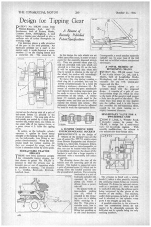
A DUMPER VEHICLE WITH INTERCHANGEABLE BUCKETS IMPROVEMENTS in the design of 1 vehicles of the dumper type are the aim of patent No. 577,711, which comes from Brooks Equipment and Manufacturing Co., Enoxville, Tennessee, U.S.A. The buckets used are interchangeable, so that one can be loaded while the other is travelling; moreover, the shape of the buckets is such that a large capacity is obtained with a reasonably low centre of gravity.
The drawing shows the rear of the vehicle and the operating gear of the bucket The bucket is supported upon a pair of pivoted arms (I), which can he swung from the loaded position into theground-level position. The actuating
mechanism is a pair of
577/1 hydraulic cylinders (2), operated by an oil pump (3), which is driven from a power take-off.
Thz piston works an intermediate rocking arm (4), which is coupled to the swinging arm via a sliding block working in a slot (5). This gives a variable ratio, low at the commencement of lifting but speeding up as the load decreases. Consequently, a much smaller hydraulic cylinder can be used than if the full load had to be lifted without mechanical advantages.
A NOVEL METHOD OF TENSIONING CHAINS
PATENT No. 578,164 comes from the Austin Motor Co., Ltd., and J. Haefel, both of Longbridge Works, Birmingham, and shows an automatic tensioner for use with timing-gear chains and the like.
The drawing shows a pair of sprockets fitted with the proposed device. It consists of a pair of synthetic-rubber rings (1), which lie close to the teeth of the sprocket and project a little into the path of the chain. The chain must thus press its way slightly into the rubber, and it is this feature that provides the self-tightening effect, caused by the chain running on a slightly increased diameter.
SEMI-ROTARY VALVE FOR A TWO-STROKE UNIT
FROM F. Lloyd, 4, Weelsby Road, Grimsby, comes, in patent No. 578,495, a design for a semi-rotary
valve for two-stroke engines. With suitable modifications, the scheme is also suitable for four-stroke units.
The cylinder is fitted with a sliding head (1), which is also partially rotated, the operating means being an eccentric ball-joint (2) driven by external means, such as a sprocket (3). Only the inlet is worked in this way, the exhaust ports being uncovered by the piston at the bottom of the stroke. The mixture, under slight pressure, is fed to a belt (4), and is admitted to the cylinder when ports 5 are brought up into line.
A possible objection to the scheme is that the combustion forces do not appear to be adequately opposed, the ball-joint and its spindle being the only resisting members.