A Daimler-Benz Combustion Head A Résumé of Patent Spedfications that
Page 60

If you've noticed an error in this article please click here to report it so we can fix it.
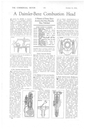
Have Recently Been Published IN patent No. 433,922, by Daimler. Benz A.G., of Stuttgart, Germany, is shown a modified combustion head which is claimed to promote easier starting and steadier running. In this scheme a spherical precombustion chamber (3) is provided with three tangential passages leading to the cylinder. The drawing, being a central section, shows but one of these (1), the others being disposed one in front and one behind that shown. The three passages are arranged fanwise, their axes
meeting at a point on the periphery of the spherical chamber.
Another point is the provision of a depression (2) in the piston crown ; the object of this is to form an auxiliary combustion chamber for that portion of the fuel which is injected directly down the central passage from the nozzle, and it is this feature that is claimed to facilitate starting.
A New American Injection Pump.
AN injection pump of the constantstroke variety is disclosed in patent No. 433,845 by Campbell, Wyant and Cannon Foundry Co., of Norton, Michigan, U.S.A. In operation, on the plunger downstroke, fuel is drawn via one-way valve 5 from the supply conduit (4), passing along passage 6
into the working space. Upon the rising of the plunger, the fuel returns along the passage (6), but this time is ejected through one-way valve 7 into the nozzle line (8). • Adjustment for output variation is obtained in the fol lowing manner:—. When the plunger rises the first action of the fuel is to lift a is accumulator plunger (3) against the pressure of a, spring, which is of a low value. No injection can occur until the movement of the accumulator piston is arrested by contact with a stoppin (2), after which the pressure rises to the injection value.
The position of the stop-pin is determined by a quirk B46 threaded sleeve carrying a pinion (9), which is under the control of a rackrod (1) of the conventional type.
Torque Converter Details.
THOSE interested in the design of torque converters should obtain a copy of patents Nos. 434,204 and 434,228, both by C. Dell, 25, Swing Gate Lane, Berkhamsted, and H. L. Read, "Netherton," Herington Grove,
Hutton Mount, Essex. In both of these patents are described various modifications in the interior-vane design, the object being to ensure that the working space contains the correct amount of fluid, having regard to conditions of temperature and working pressure.
A New Method of Valve-seat Insertion.
ACCORDING to the Cla,phani'Metallizing Co., 158, Stonhouse Street, London, S.W.4, the usual type of mechanically inserted valve seat is, for several reasons, unsatisfactory, excessive bulk and differential expansion being instanced. This concern describes in patent No. 432,679 a method of building up a valve seat by means of metal spraying.
The first operation consists of machining an angular groove (2) around the port, after which the seating is deposited by spraying with metal, such as Monel, aluminium-bronze or the like. After spraying, the surface is machined to a finish, preferably by grinding, resulting, it is claimed, in a compact hard-wearing seating that will not work loose. The disc (1) and the sleeve (3) are described as masks for localizing the stream of sprayed metal.
Preventing Roller-bearing Race Creep.
T"problem of preventing an outer race from creeping is one which all designers have to face. A means for
achieving this result without heavy gripping, with its consequent distortion, is shown in patent No. 433,309 by A. G. Elliott, Darley Dene, Belper Road, Derby. The outer race is channel-sectioned, having an inner bearing surface and two outwardlyextending flanges. These flanges overlap the .split crankcase housing, and are secured thereto by a number of small bolts (1). End-thrust plates for the rollers are also held under the bolts, the whole forming a rigid bearing having a minimum overall length.
A Bosch Injector-nozzle Modification.
WITH the object of providing an adjustable spring pressure on the needle, an improved injector design has been patented by Robert Bosch A.G., of Stuttgart, Germany. Its details are described in patent No. 433,745.
The specification states that it is often desirable to increase the loading on a fuel-operated
745 closure valve, especiallywhen the engine is being started. The • proposed method is to surmount the nozzle body with an extol': sion (3) carrying at the top a laminated spring (1) which bears on an extension of the valve (5). An internal spring (4) supplies the normal closing force, the upper leaf spring acting purely as a reinforcement when required, at other times being held out of action by a handoperated cam (2). '


