


Cummins Oil Engine Now on British Market
Page 50
Page 51
If you've noticed an error in this article please click here to report it so we can fix it.
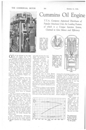
T.T.A. Company Appointed Distributor of Popular American Unit, the Leading Feature of which is a Unique Injection System, Claimed to Give Silence and Efficiency ONE of the pioneers of the highspeed oil engine, Mr. C. L. Cummins, designer of the power unit that bears his name, brought fame to his product several years ago by attaining a speed of nearly 110 m.p.h. on a racing car in which it was in stalled. More recently a Cumminsengined car has travelled at 137.195 m.p.h. and in doing so has established an oil-engine speed record which has not to our knowledge been exceeded.
These power units for transport, marine and industrial purposes are built by the Cummins Engine Co., Columbus, Indiana.
They have not, hitherto, been marketed in Great Britain, but now the Truck and Tractor Appliance Co. (Manchester), Ltd., Trafford Park, Manchester, .17, and 11!2,. Grosvenor Road, London, S-W.1, has been appointed sole distributor in this country of all types of CutArnins engine. The company plans to include a four-cylindered modelamong its exhibits at the Commercial Motor Show at Olympia next month.
This has a capacity of 448 cubic ins. (about 7.35 litres) and develops, at 1,800 r.p.m., 83 b.h.p. It is rated at 88 h.p., the bore and stroke being 44 ins, (123.82 mm.) and 6 ins. (152.4 mm.) respectively. Its weight with auxiliaries is 14 cwt., and we understand that it will be offered in Great Britain at a competitive price.
In general layout and in respect of its patented injection system the engine has not recently been greatly altered in design, but, for the benefit of those not familiar with the unique Cummins features, we will briefly describe the salient points.
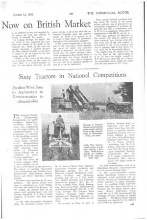
From accompanying illustrations it will be noted that in the cylinder head, between the two valves, there is a plunger operated by a third rocker
B26 and push rod from the camshaft. Its function is the actual injection of fuel.
However, properly to understand the system, we had better start at the beginning. Oil fuel is drawn through a filter from the tank by a geartype pump, and is fed at low pressure to a single metering plunger pump, similar in type to the injection pumps used on most British transport oil engines, but working at only a fraction of the pressure usually employed. The figure is between 75 and 130 lb. per sq. in.
This pump is controlled in the orthodex manner by high and low-speed governors, and the timing and quantity delivered are regulated similarly by its means.
It delivers a charge to each cylinder in turn, the distribution being effected by a simple device consisting, fundamentally, of two plates, in one of which there is a hole that coincides in turn with each of four orifices in the other.
Among the advantages of using so low a pressure is that a distributor can be employed, and it is clear that the system renders it practically impossible for unequal charges to be delivered to different cylinders. This is one big step towards smooth running.
From the distributor, four tubes lead the fuel to the head, each communicating with a passage, in which there is a small non-return ball valve. The sectional drawing shows the arrangement clearly. It will be seen that the liquid is fed to a chamber, at the bottom of which there is a pintle-type nozzle designed to discharge into the cylinder.
The volume of the chamber is controlled by the position of the plunger, mentioned earlier. Prior to -the beginning of the power stroke, this rises, as shown in the inset drawing, and, as it does
so, in addition to the fuel supplied by the pump, air from the cylinder is. sucked in through the nozzle.
In passing through the liquid, the air, which is hot, vaporizes the fuel, itself also heated by the walls of the chamber, etc. Thus, by the time the plunger descends, a gaseous mixture has been formed beneath it, and there is stated to be no liquid in the discharge into the cylinder.
Formed in the crown of the piston is an annular recess, at the centre of which there is a conical-nozzled nit cell. As the piston descends on the power stroke, a jet of air from the air chamber impinges upon the injector nozzle, by which it is spread, so as to create a high degree of turbulence throughout the combustion chamber.
Of the utmost importance is the contour of the cam, upon which depends the speed at which the injection plunger is depressed. It will be appreciated that the rapid burning conditions obtaining in the cylinder make it desirable that the charge should be injected slowly. The cam is designed to cause fuel to be supplied exactly as fast as it can be ronsurned.
Thus, steady burning continues during nearly the whole of the power stroke, and any rise of pressure to an undesirable magnitude is avoided, despite the fact that a compression ratio of 17 to 1 is employed, which gives a compression of 450-500 lb. per sq. in.
This may, perhaps, he regarded as the second step towards smooth and quiet running, and, having inspected, last week, one of the first engines to be handled by the T.T.A. concern, and seen it running light at low speed, we can vouch for its remarkable silence.
Its length from the front of the fan to the back of the bell-housing is 3 ft. 7} ins.; its height, overall is 3 ft. 6-f ins., of which 12*• ins, is below the crankshaft centre, whilst.the width over the rear bearers is 2 ft. liu,