


The Smallest Oiler Yet Produced
Page 40
Page 41
If you've noticed an error in this article please click here to report it so we can fix it.
The Victor 1-litre "Flat Twin," Installed in a Jowett 7 -cwt. Van Chassis, Gives Encouraging Results. A Satisfactory Road Performance
is Obtained
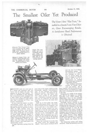
PRODUCED some two years ago as a marine and stationary unit, the Victor Cub oil engine has now been adapted for use in road vehicles. To prove its capabilities in this direction, one of these power-units, equipped with a plate clutch and a four-speed gearbox, has been installed in a light chassis and, with a pay-load of 7 cwt., was recently demonstrated.
We have tried this vehicle—an otherwise-standard Jowett van model—in and around Coventry, where we put it through its paces to ascertain its suitability for light haulage work and general-delivery duties. As our test run took place during the early development of this small oiler, we were unable to obtain really authentic figures regarding performance, but we made a rough check of the claims made by the engine manufacturer—Victor -Oil Engines, Ltd., Cox Street and Harefield Road, Coventry—and found them to be substantially correct.
A single light-alloy casting forms the 526 main body of the engine, which is of the horizontally opposed twin-cylindered type. In this, cast-iron, wet cylinder liners are inserted. The heads are detachable and carry the valves with their stems parallel to the cylinder axes. Combustion chambers of the aircell type are employed, the cell itself being removable from the main head casting.
Built up of three parts, the crankshaft is particularly sturdy. The centre section includes the two crankpins—one set on each side of the central web— whilst the bearing surfaces are casehardened to form the inner journals of roller bearings which are housed in the big-ends of the connecting-rods. The complete shaft is mounted in a roller bearing on the timing-gear side and a roller and ball bearing at the flywheel end. This ball bearing locates the crankshaft axially.
Above the crankcase is an iron casting which carries the camshaft and tappets. These operate overhead valves and the two C.A.V.-Bosch fuel-injection pumps. On the camshaft is a further cam arranged so that it can be moved along the shaft to engage the exhaust tappets and to act as a decumpressor by keeping these valves open during the compression strokes.
The overhead mechanism consists of tubular pushrods and rockers. All of these, together with the nozzles and the injection pumps, are enclosed by a light alloy cover, extending the whole length of the unit.
Occupying the middle of the timinggear side of the engine is a further light-alloy cover which encloses the duplex-chain drive to the camshaft and the single-roller chain which oper ates the water and oil pumps. ..
Particular interest attaches to the layout of the lubricating and cooling systems, for the sump (which, of courae, is bolted to the underside of the main casting) is arranged so that all the incoming cold water passes through a jacket formed at the bottom of the-oil container, and surrounds the oil pump. Water circulation is ensured by a geartype pump, delivery being effected through cored passages to the cylinder heads ; from these it flows along the cylinder barrels and thence to the radiator.
The lubricating system next claims attention. From an accessibly mounted filter, oil is led to each end of the crankshaft, where oil rings of the plainbearing-type connect with passages in the shaft itself, leading the lubricant to the two crankpin roller bearings. Another passage formed in the main casting leads to the tappet housing, which is drilled so that a pressure feed is maintained to the two camshaft bearings and to all the tappet guides.
Each tappet is hollow and is drilled radially as well as at each end, enabling oil to pass through the tappet, to the cam face at one end, and at the other to the inner ball and socket joint of the push-rod. By thus feeding the tubular push-rods with oil, the similar joints of the overhead-rocker mechanism are also copiously supplied. Further drilled passages lead to the rocker bearings.
Bore and stroke dimensions of 80 mm. and 100 mm. give a swept volume of 1,005 c.c., the power developed by the unit being 9 b.h.p. at 1,000 r.p.m., 15 b.h.p. at 2,000 r.p.m. and nearly 20 b.h.p. at :3,000 r.p.m.
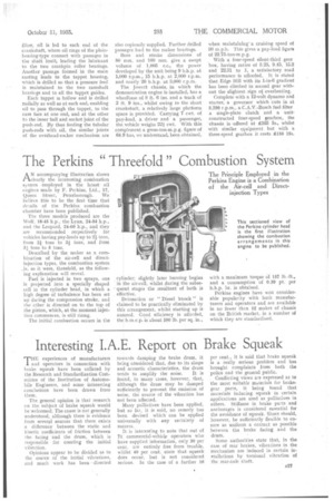
The Jowett chassis, in which the demonstration engine is installed, has a wheelbase of 8 ft. 6 ins, and a track of 3 ft, 9 ins., whilst owing to the short crankshaft, a relatively large platform space is provided. Carrying 7 cwt. of pay-load, a driver and a passenger, the vehicle weighs 224 cwt. With this complement a gross-ton-mpg. figure of 64.9 has, we understand, been obtained, when maintaining a cruising speed of 30 m.p.h. This gives a pay-load figure of 22.75-ton-mpg.
With a four-speed silent-third gear box, having ratios of 5.25, 9.45, 15.2 and 22.31 to 1, a satisfactory road performance •is afforded. It is stated that Edge Hill with its 1-in-6 gradient has been climbed in second gear without the slightest sign ot overheating.
Complete with a 12-volt dynamo and starter, a governor which cuts in at 3,250 r.p.m., a C.A.V.-Bosch fuel filter a single-plate clutch and a unitconstructed four-speed gearbox, the • chassis is -offered at 165 5s., whilst with similar equipment but with a three-speed gearbox it costs £.156 15s.