


AN .ARTICULATED TRACTOR.
Page 52
If you've noticed an error in this article please click here to report it so we can fix it.
A Résumé of Recently Published Patents.
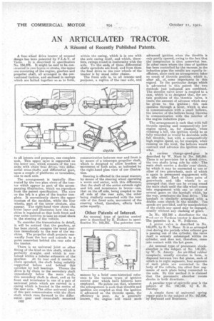
A. four-wheel drive tractor of unusual design has been patented by F.I.A.T. of Turin. It is described in specification No. 154,876. It might be said to he, constructed in two layers or strata, the upper one consisting of the engine, gearbox and propeller shaft, all arranged in the Conventional fashion, and enclosed in casings which are boltedtogether so as to form, to all intents. and purposes, one complete unit. This upper layer is supported on the lower one, which consists of the two axles with chain final drives,'two differential cross-shafts and differential gear, upon a couple of platforms or turntables, one to each axle.
The arrangement is typically illustrated by the two plan views of the tractor which appear as part of the accompanying illustration, which we reproduce from the patent specification. The view On the left is a plan of the tractor complete. It conveniently shows the upper stratum of the machine, while the four wheels, part of the lower stratum, also appear. The right-hand view shows the lower layer and illustrates how the machine is regulated so that both front and rear axles contrive to take an equal share in the steering of the vehicle.
To consider the transmission in detail, it, will be noticed that the gearbox, as has been ,stated, occupies the usual position immediately to the rear of the machine. The propeller shaft projects rearwardly from the box and extends to a point somewhat behind the rear axle of the tractor.
There is no universal joint or other fitting of the kind on this shaft, which is perfectly straight and which is contained within a tubular extension of the gearbox. At its rear end it carries a chain sprocket, the shaft being suitably supported before and behind thissprocket by ball bearings. Thence the drive is by chain to the secondary shaft immediately below the main shaft, this secondary shaft is short, and at its front end terminates 'in one of a pair of universal joints which are carried in a casing which is located in the centre of the rear axle, The other universal joint of this pair communicates with the short shaft which runs forward to the differential gear and cross-shaft mounted CU within the casing, which is in one with the axle casing itself, and which, therefore, swings round in conformity with the axle. To the ends, of these differential shafts sprockets are fixed, and from them the final drive to the rear wheels of the tractor is by usual roller chains. The front axle is, to all intents and purposes, a replica. of the rear axle, and communication between rear and front is by means of a telescopic propeller shaft, which is designed to allow freedom of movement of both axles, as indicated by the right-hand plan view of our illustration.
Steering is effected in the usual manner, by means of the steering wheel operating a worm and sector, with this difference, that the shalt of the sector extends right and left and terminates in levers—one, that an the off side, being coupled to the off side of the rear axle, the other being simila-rly connected with the near side of the front axle, movement of the steering wheel, therefore, affects both axles equally.
Other Patents of Interest.
An unusual type of ignition control gear is described by E. Dodson in specification No. 168,381. The patentee corn
mences by a brief semi-historical reference to the various types of ignition control gear which have hitherto been employed. He points out that, wherever the arrangement is such that throttle and ignition are coupled so. that the ignition is advanced as the throttle opens, the efficiency is, poor. As is generally known, the engine will stand . more
advanced ignition when the throttle is only partly opened, owing to the fact that the compression is then somewhat less. In other eases where the time of ignition has been controlled by the vacuum_iia the induction pipe the results are equally inefficient, since such an arrangement takes no count of throttle position, which is, after all, of, some importance in this -regard. In the particular design which is advocated in this patent the two methods just indicated are combined. The throttle valve lever is coupled to a cam, which is so designed that, for certain positions of the. throttle valve, it limits the amount of advance which may be given to the ignition this cam operates through a lever, Which is also in communication with a small bellows, the interior of the bellows being likewise in communication with the interior of the engine induction pipe.
The arrangement is such that with full • throttle opening and comparatively low engine speed, as for example, when climbing a hill, the ignition would be as fully retarded as would be desirable with full throttle, but with a comparatively high engine speed, as, for example, when running on the level, the bellows would contractand advance the ignition somewhat.
A curious change-speed-gear is described by W. Marx in No. 169,365. There is no provision for a direct drive, the two shafts lying side by side.-The main shaft carries a double cone clutch, by which it may be connected to one or other of two gearwheels, each of which is again in permanent engagement with an idle wheel. Each of these pairs of gearwheels and idle -wheels is 80 arranged that they can be swung rcrund the main shaft until the idle wheel comes into engagement with one or other of several gears on the layshaft which, by the way, terminates the final driveThe layshaft is similarly arranged with a double cone clutch in the middle. Ten speeds are provided, ancl by manipulation af the clutch any speed may be engaged, usually without any clashing of gears.
In No. 168.350 a distributor for the word car or Fordson tractor is described. The patentee is A, W. Fellowes.
A piston valve is described in No. 145,074, by E. V. Reno. It is so arranged that during the periods when exhaust gas is passing out of the cylinder, the valve itself is entirely submerged within its cylinder, and does not, therefore, come into contact with the hot gases.
An unusual type of pneumatic shockabsorber is the subject of No. 146,291, by W. N. Amory. An air-filled rubber receptacle, usually circular in form, is disposed between two flat plates, each ofwhich is in eight segments, four augments of each plate are connected to the body of the vehicle, the other four segments of each plate being connected to the axle. By this method it is claimed that the pneumatic absorber resists shocks in both directions.
A peculiar type of epicyclic gear is the subject • of No. 148,169, by E. H. :Develay.
A simple form of universal spring repair plate is the subject. of No. 163,006, by Reynand and Boureeret.