


Patents Completed.
Page 22
If you've noticed an error in this article please click here to report it so we can fix it.
SPEED GEAR. — Argyll Motors', Limited, and Another.—No. 26,657, dated December 21st, 1905.—The driving shaft (A) is in line with the driven shaft (B), and carries a wheel (Al). This wheel gears with a wheel bolted to a countershaft (C) ; on the other end of the countershaft. is a second wheel meshed with a wheel (K), free on the driven shaft (B). The wheels (Al and K) carry jaws (I and l respectively), and, free to slide on the ;haft (B), is a sleeve (11), carrying wheels (D anc1E). The wheel (D) has jaws (DI) corresponding to the jaws (I), and the wheel (E) has
jaws (El) corresponding to the jaws (J). Free to slide on the shaft (C) are two wheels (F, G), and a reversing wheel (not shown) is carried on a shaft which cart be moved to bring it into mesh with the wheel (DI. This gear gives four speeds and a reverse. By moving the jaws (D1) into engagement with the jaws (Ij, a direct drive is obtained, and by moving the jaws (El) into engagement with the jaws (j), and also the wheel (G) into mesh with the wheel (E), a lower speed may be obtained, whilst by sliding the Wheel (I) into mesh with the wheel (D) still another speed results. The lowest speed is obtainable when the jaws (El and j) are engaged and the wheels (I: and G) are free. To reverse, the reverse pinion is brought into mesh with the wheels (D and F) simultaneously.
VALVES.—Heckford and Another.— N. 22,491, dated November 3rd, 1905.— To provide a valve with a composite head which may be solidly secured to the stem, the stem is first reduced as at A, and then a ductile material placed thereon in the form of a sleeve (B). The whole is then welded so that the desired shape is given to the head, as shown in Fig. 2, and the ductile metal is thus made practically homogeneous with the stem. FRONT DRIVING.STEER1NG AXLE. —Becker.—No, 11,563, -dated May 17th, 1906.—The axle is divided and mounted in a carriage (3), which can be turned about a central vertical axis for steering. The end of one half-portion of the shaft carries a bevel-wheel (27), which gears with a bevel-wheel (25), and the other half carries a bevel-wheel (26) gearing with a bevelwheel (24). The wheels (24 and 25j are connected by shafts (22 and 23_ respectively) with differential gear not shown in the drawing. It will be seen that to obtain the forward drive on both road wheels (1) the bevel-wheel (24.) must rotate in the reverse sense to the bevel-wheel (25), so that the driving does not tend to turn the carriage (23). Further, the bevel of the wheels (26 and 27) is made to'coincide with a cone drawn from the road wheels as base, and having the vertical axis, about which the carriage (3) turns, as apex, so that the steering movement is not transmitted to the driving gear.
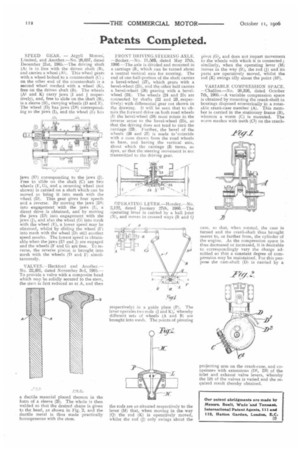
OPERATING LEVER.—Horsley.—No. 2,122, dated January 27th, 1906.—The operating lever is carried by a ball joint (N), and moves in crossed ways (R and Q respectively) in a guide plate (P). The lever operates two rods (j and K), whereby different sets of wheels (A and 13) are brought into mesh. The points of pivoting the rods are so situated respectively to the lever (M) that, when moving in the way (Q) the rod (K) is operatively moved, whilst the rod (j) only swings about the
pivot (G), and does not impart movement to the wheels with which it is connected ; similarly, when the operating lever (M) moves in the way (R), the rod (j) and its parts are operatively moved, whilst the rod (K) swings idly about the point (111).
VARIABLE COMPRESSION SPACE. —Challiss.—No. 20,326, dated October 7th, 1905.—A variable compression space is obtained by mounting the crank-shaft in bearings disposed eccentrically in a rotatable crank-case member (A). This member is carried in the stationary frame (B), whereon a worm (C) is mounted. The worm meshes with teeth (Cl) on the crank
case, so that, when rotated, the case is turned and the crank-shaft thus brought nearer to, or further from, the cylinder of the engine. As the compression space is thus decreased or increased, it is desirable to correspondingly vary the charge admitted so that a constant degree of compression may be maintained. For this purpose the cam-shaft (D) is carried by a
projecting arm on the crank-case, and cooperates with extensions (D1, D2) of the inlet and exhaust valve levers, whereby the lift of the valves is varied and the required result thereby obtained.