Albion's Latest IMBLE NIMBUS
Page 120

Page 121

Page 122

Page 123

If you've noticed an error in this article please click here to report it so we can fix it.
New Under:floor-engined Passenger Chassis has Claymore Engine and Gearbox : Short Wheelbase Gives Good Manauvrability : 32-seat Bus Tested By John F. Moon,
A.M.1.R.T.E.
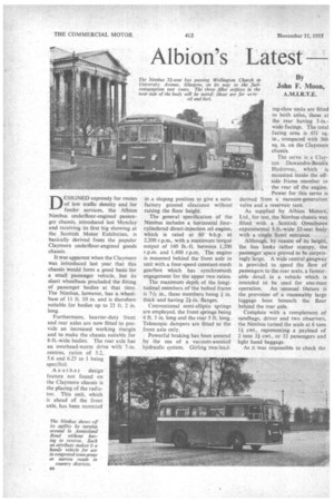
DESIGNED expressly for routes of low traffic density and for feeder services,: the Albion Nimbus underfloor-engined passenger chassis, introduced last Monday and receiving its first. big showing_at the Scottish Motor Exhibition, is basically derived from the popular Claymore underfloor-engined goods chassis.
It was apparent when the Claymore was introduced last year that this chassis would form a good basis for a small passenger vehicle, but its short wheelbase precluded the fitting of passenger bodies at that time. The Nimbus, however, has a wheelbase of 11 ft. 10 in. and is therefore suitable for bodies up to 23 ft. 2 in. long.
'Furthermore, heavier-duty front and rear axles are now fitted to provide an increased working margin and to make the chassis suitable for 8-ft.-wide bodies. The rear axle has an overhead-worm drive with 7-in. centres, ratios of 5.2, 5.6 and 6.25 to 1 being specified.
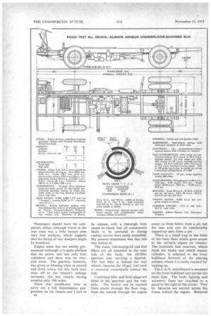
Another design feature not found on the Claymore chassis is the placing of the radiator. This unit, which is ahead of the front axle, has been mounted in a sloping position to give a satisfactory ground clearance without raising the floor height.
The general specification of the Nimbus includes a horizontal fourcylindered direct-injection oil engine, which is rated at 60 b.h.p. at 2,200 r.p.m., with a maximum torque output of 160 lb.-ft. between 1,200 r.p.m. and 1,400 r.p.m. The engine is mounted behind the front axle in unit with a four-speed constant-mesh gearbox which has synchromesh engagement for the upper two ratios.
The maximum depth of the longitudinal members of-the bolted frame is 7A. in., these members being I in. thick and having 2+-in. flanges.
Conventional semi-elliptic springs are employed, the front springs being 4 ft. 3 in. long and the rear 5 ft. long. Telescopic dampers are fitted to the front axle only.
Powerful braking has been assured by the use of a vacuum-assisted hydraulic system. Girling two-lead
ing-shoe units are fitted to both axles, those at the rear having 5-in.wide facings. The total facing area is 451 sq. in., compared with 366 sq. in. on the Claymore chassis.
The servo is a Clayton Dewandre-Bendix Hydrovac, which is mounted inside the offside frame member to the rear of the engine. Power for this servo is derived from a vacuum-generation valve and a reservoir tank.
As supplied by Albion Motors, Ltd., for test, the Nimbus chassis was fitted with a: Scottish Omnibuses experimental 8-ft-wide 32-seat body with a single front entrance.
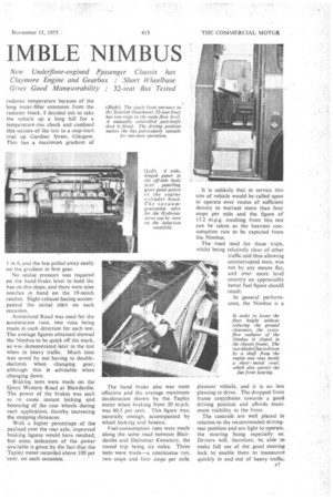
Although, by reason of its height, the bus looks rather stumpy, the passenger space proved to be surprisingly large. A wide central gangway is provided to speed the flow of passengers to the rear seats, a favourable detail in a vehicle which is intended to be used for one-man operation. An unusual feature the provision of a reasonably large luggage boot beneath the floor behind the rear axle.
Complete with a cotnpletnent of sandbags, driver and two observers, the Nimbus turned the scale at 6 tons 1+ cwt., representing a payload of 2 tons 2+ cwt., or 32 passengers and light hand baggage.
As it was impossible to check the radiator temperature because of the long water-filler extension from the radiator block, I decided not to take the vehicle up a long hill for a temperature-rise check and confined this section of the test to a stop-start trial up Gardner Street, Glasgow. This has a maximum gradient of in 6, and the bus pulled away easily on the gradient in first gear.
No undue pressure was required on the hand-brake lever to hold the bus on this slope, and there were nine notches in hand on the 19-notch ratchet. Slight exhaust hazing accompanied the initial start on each occasion.
Anniesland Road was used for the acceleration runs, two runs being made in each direction for each test. The average figures obtained showed the Nimbus to be quick off the mark, as was demonstrated later in the test when in heavy traffic. Much time was saved by not having to doubledeclutch when changing gear, although this is advisable when changing down.
Braking tests were made on the Great Western Road at Blairdardie. The power of the brakes was such as to cause instant locking Snd bouncing of the rear wheels during each application, thereby increasing the stopping distances.
With a higher percentage of the payload over the rear axle, improved braking figures wOuld have resulted; but some indication of the power available is given by the fact that the Tapley meter recorded above 100 per 'cent. on' each occasion.
The hand brake also was most effective and the average maximum deceleration shown by the Tapley meter when braking from 20 m.p.h.was 69.5 per cent. This figure was; naturally enough, accompanied by wheel locking and bounce. .
Fuel-consumption runs were made. along the same road between Blairdardie and Dalnottar Cemetery, the round trip being six miles. Three tests were made—a continuous run, two stops and four stops per mile.
It is unlikely that in service this size of vehicle would he called upon to operate over routes of sufficient density to warrant more than four stops per mile and the figure of 15.2 m.p.g. resulting from this test can he taken as the heaviest consumption rate to be expected from the Nimbus.
• The road used for these trials, whilst being relatively clear of other traffic and thus allowing uninterrupted tests, was not by any means flat, and over more level country an appreciably better fuel figure should result.
In general performance, the Nimbus is a
pleasant vehicle, and it is no less pleasing to drive. The dropped front frame contributes towards a good driving position and affords maximum visibility to the front.
The controls are well placed in relation to the recommended drivingseat position and are light to operate, the Steering being especially so. Drivers will, therefore, be able. to make full use of the good steering lock to enable them to manceuvre quickly in and out of heavy traffic..
Passengers should have no complaints, either, although travel in the rear seats was a little bumpy over very bad surfaces, which suggests that the fitting of rear dampers might be beneficial.
Engine noise was not unduly zroflounced (although it is quite obvious that the power unit has only four cylinders) and there was no rearaxle. noise. The gearbox, however, was given to whining when in second and third ratios, but this fault may wear off as the vehicle's mileage increases, the test vehicle having covered only 300 miles.
There was insufficient time to carry out a full maintenance programme on the chassis and I had to F8 be content with a thorough look round to check that all components likely to be attended to during routine service were easily accessible. My general impression was that this was indeed so.
The water, lubricating-oil and fuel fillers are all extended to the near side of the body, the oil-filler aperture also carrying a dipstick. The fuel filler is behind the rear wheels, because the 19-gal. fuel tank is mounted transversely behind the axle.
Combined filler and level plugs are fitted to the gearbox and the rear axle. The former can be reached from above through the floor trap, from the outside through the engine cover, or from below from a pit, but the rear axle can be comfortably topped-up only from a pit.
There is a small trap in the front of the body floor which gives access to the oil-bath . engine air cleaner. The hydraulic fuel reservoir, which feeds the brake and clutch master cylinders, is attached to the front bulkhead forward of the steering column, where it is easily reached for topping-up.
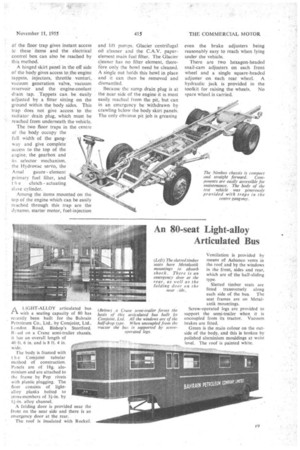
Thc-C.A.V. switchboard is mounted on the front bulkhead and carries the main fuse. The body lighting and accessory fuses are attached to a panel to the right of the driver. Two 6v. batterieS are carried across the frame behind the engine. Removal of the floor trap gives instant access to these items and the electrical control box can also be reached by this method, .
A hinged skirt panel in the off side of the body gives access to,the engine tappets, injectors, throttle venturi, vacuum generation valve, vacuum reservoir and the engine-coolant drain tap. . Tappets can, be easily adjusted by a fitter sitting on the ground within the body sides. This trap does not give access to the radiator drain plug, which must be reached from underneath the vehicle.
The two floor traps in the centre of the body occupy the full width of the gangway and give complete access to the top of the engine, the gearbox and its selector mechanism, the Hydrovac servo, the
A m al gauze element primary fuel filter, and
t h e clutch actuating slave cylinder.
Among the items mounted on the top of the engine which can be easily reached through this trap are the dynamo, starter motor, fuel-injection
and lift pumps, Glacier centrifugal oil cleaner and the C.A.V. paperelement main fuel filter. The Glacier cleaner has no filter element, there?ore only the bowl need be cleaned. A single nut holds this bowl in place and it can then be removed and dismantled.
Because the sump drain plug is at the near side of the engine it is most easily reached from the pit, but can in an emergency be withdrawn by crawling below the body skirt panels. The only obvious pit job is greasing even the brake adjusters being reasonably easy to reach when lying under the vehicle.
There are two hexagon-headed snail-cam adjusters on each front wheel and a single square-headed adjuster on each rear wheel. A hydraulic jack is provided in the toolkit for raising the wheels. No spare wheel is carried.


