 1
1 2
2 3
3 4
4 5
5 6
6 7
7 8
8 9
9 10
10 11
11 12
12 13
13 14
14 15
15 16
16 17
17 18
18 19
19 20
20 21
21 22
22 23
23 24
24 25
25 26
26 27
27 28
28 29
29 30
30 31
31 32
32 33
33 34
34 35
35 36
36 37
37 38
38 39
39 40
40 41
41 42
42 43
43 44
44 45
45 46
46 47
47 48
48 49
49 50
50 51
51 52
52 53
53 54
54 55
55 56
56 57
57 58
58 59
59 60
60 61
61 62
62 63
63 64
64 65
65 66
66 67
67 68
68 69
69 70
70 71
71 72
72 73
73 74
74 75
75 76
76 77
77 78
78 79
79 80
80 81
81 82
82 83
83 84
84 85
85 86
86 87
87 88
88 89
89 90
90 91
91 92
92 93
93 94
94 95
95 96
96 97
97 98
98 99
99 100
100 101
101 102
102 103
103 104
104 105
105 106
106 107
107 108
108 109
109 110
110 111
111 112
112 113
113 114
114 115
115 116
116 117
117 118
118 119
119 120
120 121
121 122
122 123
123 124
124 125
125 126
126 127
127 128
128 129
129 130
130 131
131 132
132 133
133 134
134 135
135 136
136 137
137 138
138 139
139 140
140 141
141 142
142 143
143 144
144 145
145 146
146 147
147 148
148 149
149 150
150 151
151 152
152 153
153 154
154 155
155 156
156 157
157 158
158 159
159 160
160 161
161 162
162 163
163 164
164 165
165 166
166 167
167 168
168 169
169 170
170 171
171 172
172 173
173 174
174 175
175 176
176 177
177 178
178 179
179 180
180 181
181 182
182 183
183 184
184 185
185 186
186 187
187 188
188 189
189 190
190 191
191 192
192 A Special Vehicle for Tar Spreading
Page 114
If you've noticed an error in this article please click here to report it so we can fix it.
ACOMPLETE tar-spraying vehicle is shown in patent No. 627,319, by Scammell Lorries, Ltd., and others, Tolpits Lane, Watford West. Based on an eight-wheeled chassis, the outfit comprises tank, heaters and spraying equipment.
The chief feature of the design is the extensive use of electrically operated auxiliaries. The tank is fitted with four, long, immersion heaters for the tar, whilst the spraying mechanism is also electrically powered. To supply the current, a generator (1) is provided, driven from the main engine by a shaft (2) connected to the front end. The electric controls are.housed in a compartment (3) at the end of the tank.
The spray-bar (4) extends across the width of the vehicle; a small handspray-head is also provided for dealing with odd corners. A feature of the scheme is that, even when not spraying, hot tar is continuously circulated through the spray-bar to prevent clogging by cooling-off. Two other patents appear on the same subject; No. 627,318, deals with the generator drive, and No. 627,320, covers the hand spray-head.
A BATTERY LEVEL INDICATOR
TO indicate the height of the electrolyte in a battery without having to remove the filler plugs and peer into a dark interior, is the purpose of a device shown in patent No. 626,576, by Joseph Lucas, Ltd., and others, Great King Street, Birmingham.
The device relies for its working on the fact that the reflective value of the end of a glass rod in liquid differs from that of one in air. In practice, two glass rods (1 and 2) are set at different levels, so that at the correct liquid height one is immersed, the other not, The lower ends are coned at 90 degrees, and the • tops are bevelled off at 45. degrees. Light passing down the wetted rod is E24 lost, but the dry one reflects the light from its coned end, and the bevelled top shows up as a bright spot. The correct level would be indicated by one bright and one black end. Two brights show insufficient liquid. and two blacks an excess. Liability of error is reduced.
A TIMBER WAGON WITH OWN LIFT DATENT No. 627,341 comes from R, G. Le Tourneau Incorporated, Peoria, Illinois, U.S.A., and deals with a vehicle for carrying timber, complete with lifting gear for dealing with the load.
A low-loading body is fitted with an inverted U-fra me (1) pivoted about point 2. It can be retracted as shown or swung into the loading position as indicated by broken lines. The swinging is performed by a complete loop of cable (3) wound on a pair of drums on an electrically operated reversible winch (4). The lifting cable (5) works from a winch driven by an electric motor (6).
In operation, the boom is used to pick up a log in the outboard position, and is then swung inwards to deposit the load on to the body. The tractive unit (7) is of the well-known Le Tourneau type having two wheels, and steering about a king-post (8).
GAS-TURBINE ROTORS I N the design of gas turbines, one of the limiting factors is the choice of material for the rotor, a part which must possess great strength at elevated tempe rature. A scheme for obtaining strength by constructional means is shown in patent No.
628,101, b y J. Atkinson, 64, Thurlow Park Road, London,
The drawing shows a rotor made according to the invention. Instead of being a solid member, it is built up from laminae firmly bolted together. The metal is a stainless steel of the I8/8 class, a variety which can be con
sidera bl y work -hardened. The actual blades are inserts, and may be held either in a " fir-tree" type of groove as shown at 1 or secured by pins (2).
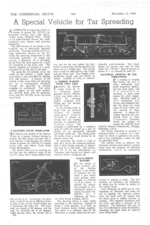
MATERIAL TESTING BY H.P. VIBRATIONS
I F a casting or forging be faulty, the fact is often undetected Until much expensive machining has been done, and it is therefore an economy to have some means for prior inspec_ tion. Methods used in this connection are X-rays and magnetic testing, but there are some types of fault which will not respond to these methods. A means for testing materials by subjecting them to highfrequency vibrations forms the subject of patent No. 628,170, from General Motors Corporation, Chicago, Michigan, U.S.A.
The device described is actually a thickness-meter; it consists of a testhead (1) which is applied to the work, and a box containing a meter (2) and an adjusting knob.
The scheme works as follows: the test-head contains piezo-electric crystals which have the property of vibrating mechanically when an alternating current is applied to them. The box contains an oscillator, the frequency of which can be varied by means of the control knob.
Each thickness of metal has its own frequency of vibration, and when the test is applied, the operator slowly turns the knob until he notices that the meter gives a sudden increase in reading. This indicates resonance with the work, and gives a measure of its thickness. The frequency dial can, in fact, be calibrated in terms of thickness, assuming the same class of material were being tested.