 1
1 2
2 3
3 4
4 5
5 6
6 7
7 8
8 9
9 10
10 11
11 12
12 13
13 14
14 15
15 16
16 17
17 18
18 19
19 20
20 21
21 22
22 23
23 24
24 25
25 26
26 27
27 28
28 29
29 30
30 31
31 32
32 33
33 34
34 35
35 36
36 37
37 38
38 39
39 40
40 41
41 42
42 43
43 44
44 45
45 46
46 47
47 48
48 49
49 50
50 51
51 52
52 53
53 54
54 55
55 56
56 57
57 58
58 59
59 60
60 61
61 62
62 63
63 64
64 65
65 66
66 67
67 68
68 69
69 70
70 71
71 72
72 73
73 74
74 75
75 76
76 77
77 78
78 79
79 80
80 81
81 82
82 83
83 84
84 85
85 86
86 87
87 88
88 89
89 90
90 91
91 92
92 93
93 94
94 95
95 96
96 97
97 98
98 99
99 100
100 101
101 102
102 103
103 104
104 105
105 106
106 107
107 108
108 109
109 110
110 111
111 112
112 113
113 114
114 115
115 116
116 117
117 118
118 119
119 120
120 121
121 122
122 123
123 124
124 125
125 126
126 127
127 128
128 129
129 130
130 131
131 132
132 133
133 134
134 135
135 136
136 137
137 138
138 139
139 140
140 141
141 142
142 143
143 144
144 145
145 146
146 147
147 148
148 A Power-operated Tilling Machine
Page 102
If you've noticed an error in this article please click here to report it so we can fix it.
A Resume of Recently Published Patent Specifications
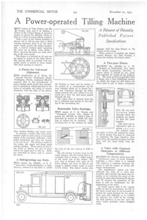
TED names of John Fowler and Co. (Leeds), Ltd., and P. R. Hasson, a citizen of the United States of America, appear in patent No. 381,504, which relates to a form of rotary-tilling machine.
Only a part of the tractor machine is shown, but it will be seen that a shaft extends rearward from it to the bevel gears which operate the tilling mechanism, a central vertical shaft operating the outer set of tilling tools, whilst a sleeve operates the inner set, both rotating at the same speed.
The frame A is pivoted at A2, and can be raised by means of the cable shown. The driving shaft is provided with universal joints to permit it being raised. The bevel gearing is enclosed.
A Piston for Universal Alignment.
THE specification of G. Hurd, 12, Rhodes Terrace, Beddington Grove, Wallington, Surrey, numbered 381,312. suggests that in the manufacture of many engines small errors may accumulate in machining, which may lead to the bores of cylinders not being in correct alignment with the sides of the piston, thus causing binding and undue wear.
To produce a piston that will accommodate itself to such errors is the main object of the invention, although a ballended connecting rod does not appear to be new to us. The piston is made in two parts, the upper and lower parts sliding together. These parts, E and P, the latter in halves, are put in place before the upper part is slid on. Dolts are described as being used to secure the parts.
A Refrigerating-van Body.
THE patent No. 380,931, of S. J. Bennetter, Tordenskjolsplass 4, Oslo, Norway, relates to a van body in which c
the interior is kept cool by means of ice packed in a compartment at; the rear, through which air is drawn by a fan and circulated through the body, rising towards the roof, where it is collected by a duct (4) and again passed through the fan.
The water that is drained from the ice is collected and assists in the cooling of the circulating air.
Renewable Valve Seatings.
THE names of C. It. Wastie and
Scammell Lorries, Ltd., appear in patent No. 380,195, in which a plan is described by means of which the seatlags of valves can be renewed. The invention lies in the method by which the ring of the new seating is held in place.
The old seating is bored away in the usual manner, but the boring tool is so arranged that it forms a slight groove at the lower end of the recess. The new ring is formed with part of its lower surface cut away so that it can engage a dished washer made of some ductile Metal. The dished washer also engages with the ring formed at the bottom of the recess.
When pressure is applied, the dished washer flattens out, thus forming a means for holding the ring in place.
A Two-part Piston.
pATENT No. 380,800, by J. W.
Howlett of Wellworthy, Ltd., Stanford Road, Lymington, describes a piston which is formed in two parts held together by means of the gudgeon pin. The head portion is provided with a flange and a long cylindrical portion on which the rings are slid before the lower part is put in place, extensions from the top part forming bosses through which the gudgeon pin passes to hold the parts together.
The rings can be alternately split to spring against the cylinder walls anl plain to form the separating lands. A waved spring ring may be employed to compress the ;rings together, thus preventing the passing of gases between them and the rings which form the lands.
A Valve with Constant Clearance at Different Temperatures.
PATENT No. 154,125, which bears the well-known name of Louis Renault, describes a valve which it is claimed will preserve a constant clearance between it and its tappet at widely different temperatures.
The specification points out that although the stem of a valve may lengthen when heated, the head also expands, so by reducing the angle of the seating to somewhere between 60 degrees and 75 degrees the expansion of the head is said to compensate for the lengthening of the stem.
It would appear that if the normal width of face be maintained, the lift of the valve would have to be increased to permit the usual freedom for the gases. And were this difficulty to be avoided by reducing the width of the seating, the high pressure of One face upon the other would probably cause excessive wear.