


THE SPRINGING OF HEAVY VEHICLES.
Page 30
If you've noticed an error in this article please click here to report it so we can fix it.
A Resume of Recently Published Patent Specifications.
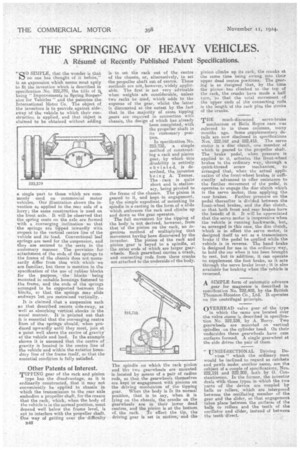
"00 SIMPLE, that the wonder is that le7 no one has thought of it before," is an expression which seems most aptly to fit the invention which is described in specification .No, 222,370, the title of it being " Improvements in Spring Suspension for Vehicles ".and the patentee, the International Motor Co.. The object of the inventors is to proVide against sidesway of the vehicle to which their construction is applied, and that object is claimed to be obtained without adding
a single part to those which are commonly used on commercial motor vehicles. Our illustration shows the invention as applied to the rear axle of a lorry; the same construction is used on the front axle. It will be observed that the spring seats on the axle are formed -with a converging .inclination so that 'the springs are 'tipped inwardly With respect to the vertical centre line of the vehicle and its load. Conventional leaf springs are used for the suspension, and they are secured to the seats in the customary manner. The provision for attachment of the ends of the springs to the frame of the chassis does not necessarily differ from that with. which we are familiar, but there is mention in the specification of the use of rubber blocks for the purpose, the blocks being mounted in suitable housings fastened to the frame, and the ends of the springs arranged to be supported 'between the blocks, so that the springs may slide endways but are restrained vertically. , It is claimed that a suspension such as that described resists side-sway, as welt as absorbing vertical shocks in the usual manner. It is pointed out that it is essential that the converging centre lines of the springs should,. when produced upwardlyuntil they meet., join at a point. well above the centre of gravity' of the vehicle and load. In the example shown it is assumed that the centre of gravity is located in the centre line of the vehicle and within the exterior boundary line of the frame itself, so that the essential condition is fully satisfied.
Other Patents of Interest.
TIPPING gear of the rack and pinion
type has the disadvantage, as it is ordinarily constructed, that it may not conveniently be applied to chassis in which the transmission to the rear axle embodies a propeller shaft, for the reason that the rack, which, when the body of the vehicle is in the normal position, must depend well below the frame level, is apt to interfere with the propeller shaft. one way of getting over the" difficulty
33413 is to set the rack out of the centre of the chassis, or, alternatively, to set the propeller shaft out of centre. These -methods are not, however, widely applicable. The first is not very advisable when weights aee considerable, unless two racks be used, which adds to the expense of the gear, whilst the latter is discounted at the outset by the fact that in the majority of cases tipping gears are required in connection with chassis, the design of which has already been completed, with the propeller shaft in its customary posi tion. , In specification No. 215,735, a simple. method'of construct.; ing a rack and pinion gear, by which. this ,disability is entirely obviated, is do. scribed, the inventor being A. Tenner. The rack is quite short and is stationary, being pivoted to the frame of the chassis. The pinion is geared to it, and kept in engagement, by the simple expedient of mounting its spindle in a casting in the form of a slide which embraces the rack and climbs up and down as the gear operates.
The full movement for the tipping of the body is not derived, however, from that of the pinion on the rack, an ingenious method of multiplying that movement having been discovered by the inventor. The pinion of the rack and pinion gear is keyed to a spindle, at the outer ends of which are larger gear, wheels. Each gearwheel carries a crank, and connecting rods from these cranks are attached to the undersideof the body.
The spindle on which the rack pinion and the two gearwheels are mounted is located by means of a pair of radius rods, so that the gearwheels themselves
are kept in engagement with pinions on•the driving mechanism of the tipping
gear. When the body is in its normal position, that is to say, when lit is lying on the chassis, the cranks on the gearwheels are in their lower dead centres, and the pinion is at the bottom of, the rack. 'To effect the tip, the driving gear is set in Motion, and the pinion climbs up its rack, the cranks at the same time being swung into their upper dead centre positions. The gearing is so designed that, by the time the pinion has climbed to the top of the rack, the cranks have made a half turn, So that the total movement of the upper ends of the connecting rods is the length of the rack plus the stroke of the cranks.
THE much-discussed servo-brake mechanism ot Rolls' Royce cars was referred to in those columns, many months ago. Some supplementary details are now disclosed in specifications Nos. 222,162 and 222,418. The servo motor is a disc clutch, one member of which is geared to the propeller shaft. The' brake pedal, when pressure is applied to it, actuates the front-wheel brakes in the ordinary way, through a quick-thread screw mechanism, so arranged that, when the actual application of the front-wheel brakes is sufficiently advanced to offer resistance to the further . movement Of the pedal, it operates to engage the disc clutch which is the servo motor, thus applying the rear brakes. Further pressure on the pedal thereafter is divided between the front-wheel brakes, and the disc, diddle so that both front and rear brakes have the benefit of it. It will be appreciated that the servo motor is inoperative wheu the vehicle is running backwards, but, as arranged in this case, the disc clutch, which is in effect the servo motor, is designed itself to act as a transmission brake if the pedal be applied while the vehicle is in reverse. The hand brake is designed for use in the ordinary way, to hold the car when it has been brought to rest, but in addition, it can operate to supplement the foot brake, as it acts through the servo brake lever ; it is also available for braking when the vehicle is reversed.
A SIMPLE form of automatic advance
gear for magnetos is described in specification No. 222,402, by the British Thomson-Houston Co., Ltd. It operates on the centrifugal principle.
• OVERHEAD valve gear of the type in which the cams are located over the valve stems is described in specification No. 222,238, by A. 'Berry. Two gearwheels are mounted on vertical spindles on the cylinder head. On their undersides these gearwheels have cam surfaces formed. A single gearwheel at the side drives the pair of them.
" UNLDIRECTIONAL Driving De vices " which the ordinary man would be inclined to regard as ratchets and pawls nudes another name, are the subject of a couple of specifications, Nos.. 222,191 and 222,202, both by G. Constantinesco. In the former, the inventor deals With those types in which the two parts' of the device are coupled by balls or rollers, .which are interposed between the oscillating member of the gear and the slider, so that engagement takes place between the surfaces; of the balls or rollers and the teeth of the oscillator and slider, instead of between the teeth -.direct.