


An Opposed-plunger Injection Pump
Page 86
If you've noticed an error in this article please click here to report it so we can fix it.
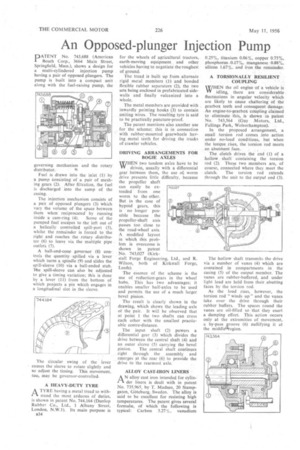
PATENT No. 743,688 (American Bosch Corp., 3664 Main Street, Springfield, Mass.), shows a design for a multi-cylindered injection pump having a pair of opposed plungers. The pump is built into a compact unit along with the fuel-raising pump, the governing mechanism and the rotary distributor.
Fuel is drawn into the inlet (1). by a pump Consisting of a pair of meshing gears (2). After filtration, the fuel is discharged into the sump of the casing. .
The injection mechanism consists of a pair of opposed plungers (3) Which vary the volume of the space between them when• reciprocated' by funning
inside a cam-ring (4). Some of the pumped fuel 'escapes to the left out of a helically controlled spill-port (5), whilst the remainder is forced to the right and reaches the rotary distributor (6) to leave via the multiple pipe outlets (7).
A ball-and-cone governor (8) controls the quantity • spilled via a lever which turns a 'spindle (9) and slides the spill-sleeve (10) via a ball-ended stub. The spill-sleeve can also be adjusted to give a timing variation; this is done by a lever (11) from the bottom of which projects a pin which engages in a longitudinal slot in the sleeve.
The circular swing of the lever causes the sleeve to rotate slightly and so adjust the timing. This movement, too, may be governor-controlled.
A HEAVY-DUTY TYRE 1-1. A TYRE having a metal tread to withstand the most arduous of duties, is shown in patent No. 744,164 (Dunlop Rubber Co., Ltd., 1 Albany Street, London, N.W.1). Its main purpose is B34
for the wheels of agricultural tractors, earth-moving equipment and other vehicles having to negotiate the roughest of ground.
The tread is built up from alternate rigid metal members (1) and bonded flexible rubber separators (2), the two sets being enclosed in prefabricated sidewalls and finally vulcanized into a whole.
The metal members are provided with inwardly pointing hooks (3) to contain uniting wires. The resulting tyre is said to be practically puncture-proof.
The patent mentions also another use for the scheme; this is in connection with rubber-mounted gearwheels having metal teeth for driving the tracks of crawler vehicles.
DRIVING ARRANGEMENTS FOR BOGIE AXLES 'WHEN two tandem axles have to be VY driven, usually with a differential
gear between them, the use ot worm drive presents little difficulty, because the propeller shaft can easily be extended from one worm to the other. But in the case of hypoid gears, this is no longer possible because the propeller-shaft axis passes too 'close to the road-wheel axis. A modified layout in which this problem is overcome is shown in patent No. 743,027 (K irkstall 'Forge Engineering, Ltd., and R. Wilson, both of Kirkstall Forge, Leeds).
The essence of the scheme is the use of reduction-gears in the wheel hubs. This has two advantages; it enables smaller half-axles to be used and permits the use of a much larger bevel pinion.
The result is clearly shown in the drawing, which shows the leading axle of the pair. It will be observed that at point I the two shafts can cross each other with the smallest practicable centre-distance.
The input shaft (2) powers a
differential gear (3) which divides the drive between the central shaft (4) and an outer sleeve (5) carrying the bevel
pinion. The central shaft continues right through the assembly and emerges at the rear (6) to provide the drive to the rearmost axle.
ALLOY CAST-IRON LINERS AN alloy cast iron intended for cylinder liners is dealt with in patent No. 735,965, by T. Madsen, 20 Stampgaten, Goteborg, Sweden. The alloy is said to be excellent for resisting high temperatures. The patent gives several formula, of which the following is typical: Carbon 3.27%, vanadium 0.25%, titanium 0.06%, copper 0.75%, phosphorus, 0..17%, Manganese 0..88%, silicon 1.67%; and iron the remainder.
A TORSIONALLY RESILIENT COUPLING
WHEN the oil engine of a vehicle is idling, there are considerable fluctuations in angular velocity which are likely to cause chattering of the gearbox teeth and consequent damage. An engine-to-gearbox coupling claimed to eliminate this, is shown in patent No. 743,564 (Guy .Motors, Ltd., Fallings Park, Wolverhampton). .
In the proposed arrangement, a small torsion rod comes into action under no-load conditions, but when the tongue rises, the torsion. rod meets an abutment face.
The clutch drives the end (1) of a hollow shaft containing the torsion rod (2). These two members are, of course, connected where they meet the clutch. The torsion rod extends through the unit to the output end (3).
The hollow shaft transmits the drive via a number of vanes (4) which are contained in compartments in the casing (5) of the output member. The vanes are rubber-buffered, and under light load are held from their abutting faces by the torsion rod.
As the load rises, however, the torsion rod "winds up" and the vanes take over the drive through their rubber buffers. The spaces round the vanes are oil-filled so that they exert a damping effect. This action occurs only at the extremities of movement, a by-pass groove (6) nullifying it at the middle*egion.