


Patents Completed.
Page 20
If you've noticed an error in this article please click here to report it so we can fix it.
MOTOR RAIL TRAINS.—Henson and the Daimler Motor Co.—No. 8342, dated 6th April. 1910.—This specification describes a propelling mechanism for bogie
vehicles running on rails, and has for its object to provide means in which the angular displacement of the driving shaft, when rounding curves, is reduced to a minimum. A motor which may be an internal-combustion or an electric motor is preferably mounted with its axis at right-angles to the road-wheel axis, and a right-angled transmission gear is arranged on the bogie axle and remote from the motor. The connection between the motor and the transmission gearbox is effected by means of a universal-jointed shaft, and in order that the angular displacement of this shaft may be a minimum' the joint in the coupling shaft is placed approximately beneath the swivelling pin of the bogie_ In some cases, two complete power units are arranged to drive, one on each bogie ; in this case the middle of the coupling shaft is arranged beneath the bogie swivelling pin, so that, when the vehicle is rounding a curve, the angles made by the coupling, shaft and the driving and driven shafts are equal. When it is desirable to keep the transmission shaft horizontal, the idle bogie wheel may be made smaller to allow the transmission shaft to clear its axle.
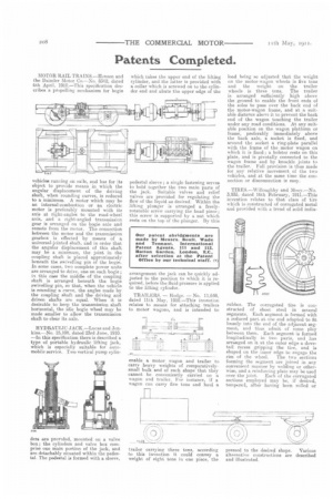
HYDRAULIC JACK.—Lucas and Jenkins.—No. 15,108, dated 23rd June, 1910. —In this specification there is described a type of portable hydraulic lifting jack, which is especially suitable for automobile service. Two vertical pump cylin ders are provided, mounted on a valve box; the cylinders and valve box comprise one main portion of the jack, and are detachably situated within the pedestal. The pedestal is formed with a sleeve, which takes the upper end of the lifting cylinder, and the latter is provided with a collar which is screwed on to the cylinder end and abuts the upper edge of the pedestal sleeve; a single fastening serves to hold together the two main parts of the jack. Suitable valves and relief valves are provided for regulating the flow of the liquid as desired. Within the lifting plunger is arranged a freelyrotatable screw carrying the bead piece; this screw is supported by a nut which rests on the top of the plunger. By this arrangement the jack can be quickly ad justed to the position to which it is required, before the fluid pressure is applied to the lifting cylinder.
TRAILERS. — Hodge. — No. 11,648, dated 11th May, 1910.—This invention relates to means for attaching trailers to motor wagons, and is intended to
enable a motor wagon and trailer to carry heavy weights of comparativelysmall bulk and of such shape that they cannot be conveniently carried on a wagon and trailer, For instance, if a wagon can carry five tons and haul a
trailer carrying three tons, according to this invention it could convey a weight of eight tons in one piece, the
load being so adjusted that the weight on the motor-wagon wheels is five tons and the weight on the trailer wheels is three tons. The trailer is arranged sufficiently high above the ground to enable the front ends of the soles to pass over the back end of the motor-wagon frame, and at a suitable distance above it to prevent the back end of the wagon touching the trailer under any road conditions. At any suitable position on the wagon platform or frame, preferably immediately above the back axle, a socket is fixed, and around the socket a ring-plate parallel with the frame of the motor wagon on which it is fixed; a bolster rests on this plate, and is pivotally connected to the wagon frame and by knuckle joints to the trailer. Full provision is thus made for any relative movement of the two vehicles, and at the same time the connection or disconnection is easy.
TIRES.—Willoughby and Mooy.—No. 3,935, dated 16th February, 1911.—This invention relates to that class of tire which is constructed of corrugated metal and provided with a tread of solid india rubber. The corrugated tire is constructed of sheet, steel in several segments. Each segment is formed with a reduced part at one end adapted to fit loosely into the end of the adjacent segment, and thus admit of sonic play between them. Each segment is formed longitudinally in two parts, and has arranged on it, at the outer edge a dovetail recess gripping the tire, and is shaped on the inner edge to engage the
rim of the wheel. The two sections forming the segment are joinevi in any convenient manner by welding or otherwise, and a reinforcing plate may be used
over the joint. Each of the corrugated sections employed may be, if desired, tempered, after having been rolled or pressed to the desired shape. Various alternative constructions are described and illustrated.