


Tractors in the W.D. Trials.
Page 4
Page 5
If you've noticed an error in this article please click here to report it so we can fix it.
TheStewart System.
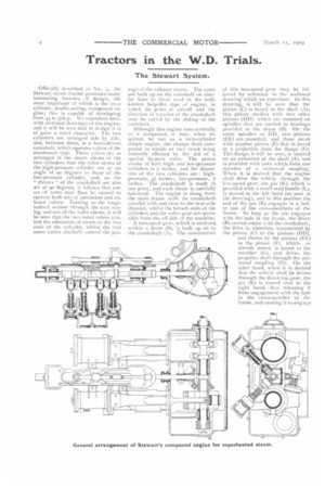
Officially described as No. 3, the Stewart steam tractor possesses many interesting features of design, the most important of which is the twocylinder, double-acting, compound engine; this is capable of developing from 45 to 50h.p. We reproduce herewith sectional drawings of the engine, and it will be seen that in design it is of quite a novel character. 1 he two cylinders are arranged side by side, and, between them, is a bevel-driven camshaft, which operates valves of the mushroom type. These valves are so arranged in the steam chests of the two cylinders that the valve stems of the high-pressure cylinder are at an angle of 90 degrees to those of the low-pressure cylinder, and, as the " throws " of the crankshaft are also set at 90 degrees, it follows that one set of cams may thus be caused to operate both sets of admission and exhaust valves. Turning to the longitudinal section through the vim casing and one of the valve chests, it will be seen that the two inner valves ccntrol the admission of steam to the two ends of the cylinder, whilst the two outer valves similarly control the pas_ sage of the exhaust Steal11. The cams are built up on the camshaft on similar lines to those used in the wellknown Serpollet type of engine, in which the point ot cut-off and the direction of rotation of the crankshaft may be varied by the sliding of the camshaft.
Although this engine runs normally as a compound, it may, when required, be run as a twin-cylinder simple engine, the change from compound to simple or vice versa being instantly effected by the aid of a special by-pass valve. The piston stroke of both high and low-pressure cylinders is 7 inches, and the diameters of the two cylinders are : highpressure, 41 inches ; low-pressure, 7 inches. The crankshaft is made in One piece, and each throw is carefully balanced. The engine is slung from the main frame with its crankshaft parallel with and close to the near-side channel, whilst the breach ends of the cylinders and the valve gear are accessible from the off side of the machine.
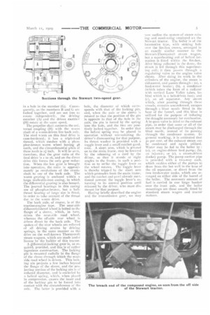
A two-speed gear, which is enclosed within a drum (1131, is built up on to the crankshaft (A). The construction of this two-speed gear may be followed by reference to the sectional drawing which we reproduce. In this drawing, it will be seen that the pinion (C) is keyed to the shaft (A); this pinion meshes with two other pinions (DD), which are mounted on spindles that are carried in bearings provided in the drum (B). On the same spindles as DD, two pinions (EE) are mounted, and these mesh with another pinion tF) that is keyed to a projection front the flange (G). This flange, it will be seen, is centred on an extension of the shaft (A), and is provided with jaws which form one member of a universal coupling. When it is desired that the engine shall drive the vehicle through the low-six:ed gear, the pin (K), which is provided with a small stud handle (L), is moved to the left hand (as seen in the drawing), and in this position the end of the pin (K) engages in a hole in one of the cross-members of the 'frame. So long as the pin engages with the hole in the frame, the drum (13) cannot rotate with the crankshaft ; the drive is, therefore, transmitted by the pinion (C) to the pinions (DD), and thence by the pinions (EE) to the pinion (F), which, as already stated, is keyed to the member (G), and drives the propeller shaft through the universal coupling (11). On the other hand, when it is desired that the vehicle shall be driven through the direct top gear, the pia (K) is move.d over to the right hand, thus releasing it from engagement with the hole in the cross-member of the frame, and causing it to engage in a hole in the member (G). Consequently, as the members B and G are locked together, and are not free to rotate independently, the driving member (A) and the driven member (H) rotate at the saute speed.
The propeller shaft connects the universal coupling (H) with the worm shaft of a worm-driven live back axle. The steel worm on this final drive is case-hardened; it has a triple-lead thread, which meshes with a phosphor-bronze worm wheel having 48 teeth, and the circumferential pitch of these teeth is ri inch. It will be seen, therefore, that the gear ratio of the final drive is i to 16, and on the direct drive this forms the only gear reduction. When the low gear is brought into operation, the ratio is approximately 30 revolutions of the crankshaft to one of the back axle, The worm gearing is enclosed within a large malleable-iron casing, in which the differential gearing is also housed. The journal bearings in this casing are of phosphor-bronze, but a ballthrust bearing of large size is fitted, in order to take account of the thrust due to the worm drive.
The back axle, of eourse, is of the traction-engine type. The near-side differential-bevel wheel is bolted to the flange of a sleeve, which, in turn, drives the near-side road wheel, whereas the off-side rear wheel is driven direct by the back axle. The spokes of the rear wheels are relieved of all driving strains by driving springs, in the same manner as the drive on the well-known Thornycroft steam wagons, which are made under license by the builder of this tractor.
A differential-locking gear is, as re quired, provided, and this is of rather ingenious construction, The locking pin is mounted radially in the flange of the sleeve through which the nearside road wheel is driven. This locking pin projects a few inches beyond the flange of the sleeve, and the projecting portion of the locking pin is of reduced diameter, and is encircled lw a helical spring, which, when placed in compression, causes the inner end of the lockine pin to be forced into contact with the circumference of the axle. The latter is provided with a hole, the diameter of which corresponds with that of the locking pin, and, when the axle or the sleeve is rotated so that the position of the pin is opposite to that of the hole in the axle, the pin is forced by the spring into the hole, and the two are positively locked together. In order that the helical spring may he placed in operation without necessitating the driver's dismounting for that purpose, its thrust washer is provided with a toggle lever and a small ratchet quadrant. A short arm, which is pivoted on to the main frame, may be lowered by the releasing of a cord by the driver, so that it stands at right angles to the frame, in such a position as to strike the toggle lever as ihe wheel rotates. The toggle lever is thereby tripped 4 the short arm which protrudes from the main frame, and the ratchet and pawl already mentioned prevent the toggle lever's returning to its normal position until released by the driver, who must dismount for that purpose.
Haying briefly described the engine and the transmission gear, we may
now outline the system of steam raising and condensing employed on the Stewart tractor. The boiler is of the locomotive type, with stoking hole over the fire-box crown, arranged in an exactly similar manner to the Stewart-Thornycroft steam wagon, but a superheating coil of helical formation is fitted within the fire-box. After being collected in the dome, the steam is led through this superheating coil ; it then passes through a regulating valve to the engine valve chests. After doing its work in the cylinders of the engine, the steam is exhausted, and passes through : (a), a feed-water heater ; (b), a condenser (which takes the form of a radiator with vertical Lune Valley tubes, behind which is a belt-driven fan); and (c), an oil separator. Any steam which, after passing through these vessels, remains uncondensed, escapes through a blast nozzle fitted in the base of the funnel, and this blast is utilised for the purpose of inducing the draught necessary for combustion. A by-pass valve is rated to the exhaust pipe, in order that some or all of the steam may be discharged through the blast nozzle, instead of its passing through the condenser system. In general working, it is estimated that 5o per cent, of the exhaust steam can be condensed and again utilised. Water may be fed to the boiler by : (a), an engine-driven feed pump; (b), an injector; or (c), a steam-driven donkey pump. The pump suction pipe is provided with a two-way cock, which enables either of the pumps to draw from the hot well in the base of the oil separator, or direct from the two fresh-water tanks, which are arranged on either side of the barrel of the boiler. The necessary amount of fuel is carried in one large bunker over the front axle, and the boiler mountings are those usually fitted by standard steam wagon and tractor makers.