


An Unusual Oil Engine
Page 64
If you've noticed an error in this article please click here to report it so we can fix it.
A Rdsurne of Patent Specifications that Have Recently Been Published. ANeilengine claimed to have a high specific output, a clean exhaust, and a cylinder head free from the complications of valve arrangements, forms the subject of patent No. 465,149, C. H. Alston, Ascerton House, Sidmouth Devon. At first glance the accompanying drawing suggests that this engine is of the two-stroke variety, but this is not the case, the power strokes occurring alternately. A rotary valve (2) is employed, containing two passages (inlet and exhaust) which connect alternately with a port (1) in the cilinder, wall. In addition, a scavenge port (3) provides an air blast from a blower.
The sequence of operations is as follows :—The piston. descends on the power stroke, passing port 1, which remains closed by the rotary valve. Near stroke bottom the valve opens this port, followed immediately by the uncovering of the scavenge port. A blast of air follows, as shown by the arrows, and then the piston rises on an id:e compression stroke. The next descent is a suction stroke, drawing in a partial charge of air from the rotary valve, reinforced by a supercharge from the scavenge port, after which norm,a1 compression and injection take place.
Novel Inlet Valve.
TO direct the incoming charge in an orderly manner, instead of a chaotic swirl, is the object of the design of inlet valve shown by J. Blanchet, 41, Rue Vital, Paris, in patent No. 465,261. The valve is provided with a partial skirt (2) on the underside SO that the gas flow is obstructed on one side, and as a result flows in sweeping lines, as shown by the arrow. The inventor states that this skirt alone is unsatisfactory, owing to the out-of-balance outline giving rise to bending moments, and proposes the addition of a counterbalancing mass (1) of streamline contour.
An Injection Pump with Novel Regulation.
rri-4E design of injection pump shown 1 in patent No. 463,805,.:, has two novel features—an mausual output regulator, and provision for lubricating the plunger. The patentee is J. Puurmann, 142, Boulevard de Grenelle, Pads.
The .plunger works on the variablestroke system, this being adjustable from zero to full delivery by a simple lever movement.. A rocking lever is pivoted on a fixed stud (2) and carries at its other end a roller (6) which en
gages with the cam. On the roller bearing is pivoted a second lever (5) which is free to oscillate, being limited only by the pressure of the pump plunger and a movable abutment (4). This is slidable by means of lever 5 and, in the position shown, is set for zero delivery:, leVer 5. Merely oscillating in
134,3 a see-saw manner without moving the pump plunger. Upon sliding pivot 4 to the right, however, the plunger is re
ciprocated according to the• amount of set-over.
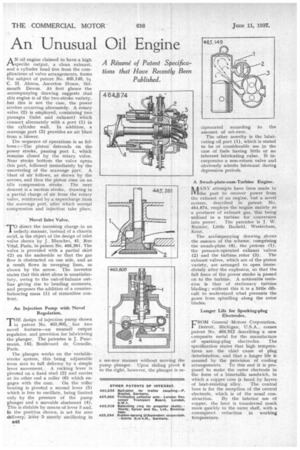
The other novelty is the lubricating oil port (1), which is stated to be of considerable use in the case of fuels having little or no inherent lubricating value. It incorporates a non-return valve and obviously admits lubricant during depression periods, A Swash-plate-cum-Turbine Engine.
l‘AANY attempts have been made inI.V.1the past to recover power from the exhaust of an engine, but a novel system, described M. patent No. 464,874, employs the engine mainly as a producer of exhaust gas, this being utilized in a turbine for conversion into power. The patentee is J. W. Rainier, Little Barfield, Westerham, Kent.
The aceOmpanying drawing shows the essence of the scheme, 'comprising the swash,plate (4), the pistons (1), the pressure-operated exhaust valves (2) and the turbine. rotor (3). The exhaust valves, which are of the piston variety, are arranged to open immediately after the explosion, so that the full force of the power stroke ig passed on to the turbine. A noticeable omisskin is that of stationary, turbine bIading ; without this it is a little dflicult to understand what prevents the gases from spiralling along the rotor blades.
Longer Life for Sparking-plug Electrodes.
FROM General -Motors Corporation, Detroit, Michigan, U.S.A., comes patent No. 464.912 describing a new composite metal for the manufacture of' sparking-plug electrodes. :Ibe specification states that high temperatures are the chief cause of plug deterioration, and that a longer life ic assured by the provision of cooling arrangements. To this end it is proposed to make the outer electrode in the form of a bimetallic sandwich, in which a copper core is faced. by layers
of heat-resisting alloy. The central bore is for the reception of the central electrode, which is of the usual con struction, By the interior use of copper, the heat is transferred much more quickly to the outer shell, with a consequent reduction in working temperature.