


A DENNIS ENGINE SUSPENSION
Page 72
If you've noticed an error in this article please click here to report it so we can fix it.
A R6stund of Recently Published Patent Specifications.
WHAT well-known concern, Dennis 1 Brothers, Ltd., of Guildford, in its specification No, 311,068, describes a means whereby engines and other units may be suspended without any rigid
connection with the frame: Springs acting in opposite directions on bolts are pro -sided so that the engine or other unit is free to move to a slight extent in either direction, as indicated in an accompanying iliustra/tion. So far, there 's nothing new in the design, but the point claimed as novel lies in the prevention of roll, or reaction to torque.
The means by which this end is obtained are indicated in the drawing of the end view of an engine. Iii this will be seen a bracket, to which is connected a
hinged rod which can slide through another bracket fixed to some part rigidly connected with the frame and provided with springs acting in oppo
site directions. This forms a centralizing device, which can yield to sudden shocks, but which normally retains the engine in an upright position.
A Novel Hydraulic Brake.
TRADING as Automotive Products Co., Messrs. E. B. Boughton, Willie Emmett, D. T. Brock and Andre Jean Serve describe in their patent No. 311,015 a brake of the hydraulic type containing a novel feature. The specification points out that with brakes of the ordinary two-shoe type, in which the shoes are forced apart by means Of pressure derived from pistons working in the same cylinder, an even pressure is brought to bear on both shoes, but, owing to the inclination of elle shoe to cling to the drum, a servo effect Is produced in that shoe, as indicated by the arrow in an accompanying illustration, whilst in the other shoe an anti-servo effect is produced. The result is uneven wear on the facings. To overcome this defect the inventors provide a cylinder in which two diameters of piston work, the larger ever. coining the anti-servo effect.
B46
A Simple Pressure Pump. THE pump described in specification
No. 303,147 by Hugo Junkers, of Dessau, Germany, is mentioned as being suitable for pumping non-lubri eating fluids at comparatively low pressures. The main featnre is the arrangement whereby lubricant can be introduced at high pressure by me: ns of the pipe shOwn in the lower view of the drawings.
It would appear to us that a pump constructed on these lines would form a very simple and efficient type for supplying lubricating oil. The arrow indicates the direction of rotation of the crank, whilst those arrows in the pipes indicate the direction of the suction and delivery of the liquid. The oscillating member diverts the opening from one tube to the other, while sucking and delivering. The point which apeals to us is that there are no valves to cause failure.
A Simple Refuse-collecting Body.
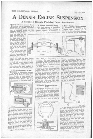
THE problem of securing the perfect body for. house-refuse collection does not appear to us to be entirely solved by the invention of Richard Turner, of Preston, in his patent No. 311,053, in which is described a bqdy provided with chutes at the side and a flap, this dropping after every binful of refuse is shot in. A New Timken Improvement.
IN specification No. 304,992, by the Timken. Roller Bearing Co., of America, an interesting detail improvement is described in the well-known Timken taper-roller bearing. The rollers of this bearing have for some time been made without heads, the larger end of each being flat and bearing against a collar thrown up from the inner cone; The end of the roller presses against the collar and ensures the rollers keeping an axial alignment with the cone.
The specification points out that the flat surface of the end of the roller and the face of the collar against which it heirs were likely in some cases to cause wear to take place more rapidly than is desirable, the flat face of the roller tending to scrape the lubricant from the face of the collar.
In the present invention the face of the collar is slightly curved, as shown in the full line in the larger view, iñ stead of the dot-and-dash line (BB), which represents the previous form, the line AA representing the angle of the cone on which the roller bears. The smaller view shows in section the assembly of the roller and the inner and outer cones.
The scraping away of lubricant referred to is particularly undesirable when grease is used. The fluid nature of oil helps it to run back on to the wearing surfaces, but heavier materials cannot do so oWing to the very small apertures available between the milers and the races.