


A Résumé of Recently Published Patent Specifications
Page 54
If you've noticed an error in this article please click here to report it so we can fix it.
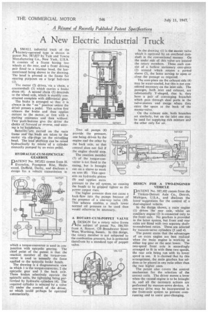
A New Electric Industrial Truck
A SMALL industrial truck of the rlbattery-operated type is shown in patent No. 587,027 by Yale and Towne Manufacturing Co., New York, U.S.A. It consists of a frame having two wheels at the rear, and a front driving pair fitted to a traction head, the lastmentioned being shown in the drawing. The head is pivoted in the frame for steering puiposes on a large ball-race (1).
The motor (2) drives, via a chain, a countershaft (3) which carries a brake drum (4). A second chain (5) descends to the wheel axle, which is sturdily constructed complete with differential gear.
The brake is arranged so that it is always in the " on " position unless the driver presses a pedal. This action first releases the brake and then applies current to the motor, at first with a starting resistance and then without. Two push-buttons give thern driver the choice of forward or reverse, and steering is by handlebars.
Batteries :are carried on the main frame and the leads are taken to the motor via slip-rings' on the swivelling head. The loadplatfOrm can be raised hydraulically by means of a cylinder manually pumped by an extra pedal.
HYDRAULIC-CUM-EPICYCLIC GEARBOX
PNo. 587,021 comes from H. Evernden, Frampton Rise, Hazlewood, Duffield, Derby, and discloses a design for a vehicle transmission in
which a torque-converter is used in conjunction with epicyclic gearing. The chief point of the patent is that the reaction member of the torque-converter is used to intensify the force applied to the epicyclic brake bands.
The drawing is a diagrammatic view in which 1 is the torque-converter, 2 the epicyclic gear and 3 the back axle. Three brakes selectively operate the epicyclic units, the tightening being performed by hydraulic cylinders (4). The equired cylinder is selected by a valve (5) under the control of , the driver, or which could perhaps be operated automatically. Two oil pumps (6) provide the pressure, one being driven by the engine and the other by the back axle, so that control does not fail if the engine should stop.
The reaction member (7) of the torque-converter is not fixed to the casing, but is brought out on a sleeve to work an arm (8). This operates an hydraulic piston (9) and applies extra pressure to the oil system, so causing the bands to be gripped tighter as the power output rises.
The higher pressure does not cause a back-flow into the pumps because of the presence of a one-way valve (10). This scheme enables, a much lower normal oil pressure to be used than would otherwise be necessary.
A ROTARY-CUM-POPPET VALVE A DESIGN for a rotary valve forms
the subject of patent No. 586,703 from A. Boorer, 120 Broadwater Street West, Worthing, Sussex. In this design, the rotary member is not subjected to the combustion pressure, but is protected therefrom by a standard type of poppet valve. In the drawing (1) is the master valve which is operated by an overhead camshaft in the conventional manner. On the under side of this valve are located the rotary members. These each consist of a hollow stationary core-piece (2) around which rotates a ported sleeve (3), the latter serving to open or close the passage as required.
The core-piece on the exhaust side (4) may be water-cooled, but this is not considered necessary on the inlet side. The passages, both inlet and exhaust, are substantially Y-shaped, that is, they have a pair of converging branches which pass through dual ports in the valve-sleeves and merge where they enter the space at the back of the master-valve.
On the exhaust side, both branches act similarly, but on the inlet one may be used for supplying rich mixture and the other only for air.
DESIGN FOR, A TWO-ENGINED VEHICLE
PATENT No. 587,102 comes from the Timken-Detroit Axle Co., Detroit, Michigan, U.S.A., and discloses the latest suggestions for the control of a dual-engined vehicle.
in the design shown, a main engine (1) drives the rear axle, whilst an auxiliary engine (2) is connected only to the front axle. No gearbox is provided in the latter system, but front and rear axles are fitted with two separate shaftto-roadwheel ratios. These are selected by vacuum-servo cylinders (3 and 4).
The patent states that the advantages of an extra engine are best realized when the main engine is working in either top gear or the next lower. The two-speed front axle is accordingly arranged to fit in with these two speeds, the rear axle being run with its lower speed in use. It is claimed that by this arrangement, the main gearbox has seldom to be placed in any ratio other than the two higher ones.
The patent also covers the control mechanism for the selection of the correct ratio. The driver moves a lever when the second engine is to be brought in, and all the necessary actions are performed by vacuum-servo devices. A one-way drive may be incorporated in the front-axle system to prevent overrunning and to assist gear-changing.