


HINTS ON MAINTENANCE.
Page 28
Page 29
If you've noticed an error in this article please click here to report it so we can fix it.
How to Get the Best Out of a Vehicle, to Secure Reliability and to Avoid Trouble.
CONTRIBUTIONS ONTRIBUTIONS are invited for this page from fleet managers, drivers, garage foremen, and mechanics, works staff and draughtsmen, and will be paid for on a generous scale. Every system, make, and type of commercial motor vehicle will he dealt with, and the matter should be written with a view to the disclosure of workshop and garage practice in the maintenance of a vehicle—practices which, whit they may be quite normal, are peculiar to ehe particular vehicle and may not be generally known to those respOnsible for its running. Expedients and suggestions for overcoming roadside and other troubles are, covered in the following page, dealing with letters from our driver and mechanic readers. Communications should be addressed to "The Editor, The Commercial Motor, 7-15, Rosebery Avenue, London, RCA."
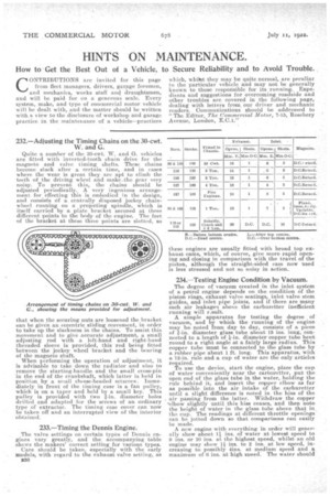
232.—Adjusting the Timing Chains on the 30-cwt. W. and G.
Quite a number of the 30-cwt. W. and G. vehicles are fitted with inverted-tooth chain drive for the magneto and valve timing shafts. These chains become slack after a certain time, and in cases where the wear is great they are apt to climb the teeth of the driving wheel and make-the gear very noisy. To prevent this, the chains should be adjusted periodically. A very ingenious arrangement for effecting this is embodied in the design, and consists of a centrally disposed jockey chainwheel running on a projecting spindle, which is itself carried by a plate bracket secured at three different points to the body of the engine. The feet of the bracket at these three points are slotted, so
that when the securing nuts are loosened the bracket can be given an eccentric sliding movement, in order to take up the slackness in the chains. To assist this movement and to give accurate adjustment, a small adjusting rod with a left-hand and right-hand threaded sleeve is provided, this rod being fitted between the jockey wheel bracket and the bearing of the magneto shaft. When performing the operation of adjustment, it is advisable to take down the radiator and also to remove the starting-handle and the small cross-pin in the end of the crankshaft, which latter is held in position by a small cheese-headed setscrew. Lnmediately in front of the timing case is a fan pulley, -which is on a taper and held by a small key. This pulley is provided with two Uri. diameter holes drilled and adapted for the screws of an ordinary type of extractor. The timing case cover can -now be taken off and an interrupted view of the interior obtained.
233.—Timing the Dennis Engine.
The valve settings on certain types of Dennis engines vary greatly, and the accompanying table shows the makers' correct setting for various types. Care should be taken. especially with the early models, with regard to the exhaust valve setting, as B30 these engines are usually fitted with broad top exhaust earns, which, of course, give more rapid opening and closing in comparison with the travel of the piston, although the straight-sided earn now used is less stressed and not so noisy in action.
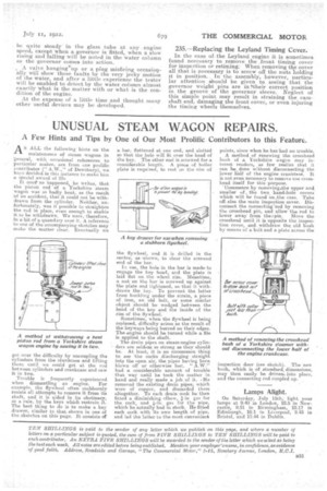
234.—Testing Engine Condition by Vacuum.
The degree of vacuum created in the inlet system of a, petrol engine depends on the condition of the piston rings, exhaust valve seatings, inlet valve stem guides, and inlet pipe joints, and if there are many such air leakages above the carburetter inefficient running will result-.
A simple apparatus for testing the degree of vacuum, and by which the running of the engine may be noted !Tom day to day, consists of a piece of i-in. diameter glass tube about 15 ins, long, connected to a length of iein. diameter copper tube bent round to a right angle at a fairly large radius. This copper tube must be connected to the glass tube by a rubber pipe about 1 ft. long. This apparatus, with a 12-in. rule and a cup of water are the only articles required. To use the device, start the engine, place the cup of water conveniently near the carburetter, put the open end of the glass tube in the water, holding the rule behind it, and insert the capper elbow as far as possible into the air intake of the carburetter until a slight difference is noted in the hiss of the air passing from the latter. Withdraw the copper -elbow slightly until this hiss ceases, and then note the height of water in the glass tube above that in the cup. The readings at different throttle openings can be jotted down so that comparisons can easily be made.
A new engine with everything in order will geneie ally show about 11 ins, of water at lowest speed to 9 ins. or 10 ins, at the highest speed, whilst an old engine may show l ins. to 2 ins, at low speed, increasing to possibly 4ins. at medium speed and a maximum of 6 ins, at high speed. The water should
be quite steady in the glass tube at any engine speed, except when a governor is fitted, when a stow rising and falling will be noted in the water column as the governor comes into action.
A valve hanging up or a plug misfiring occasionally will show these faults by the very jerky motion of the water, and after a little experience the tester will be enabled to detect by the water column almost exactly what is the matter with or what is the condition of the engine.
At the expense of a little time and thought many other useful devices may be developed.
235.—Replacing the Leyland Timing Cover.
In the case of the Leyland engine it is sometimes found necessary to remove the front timing cover for inspection or retiming: When removing the cover all that is necessary is to screw off the nuts holding it in position. In the assembly, however, particular attention should be given to seeing that the governor weight pins are in their correct position in the groove of the governor sleeve. Neglect of this simple point may result in straining the camshaft end, damaging the front cover, or even injuring the timing wheels themselves.