


Fuel Cooler to Prevent Vapour Locks
Page 76
If you've noticed an error in this article please click here to report it so we can fix it.
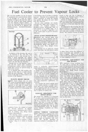
I N very hot weather it is by no means uncommon for a petrol-driven vehicle to be brought to a stop by vapour bubbles forming in the fuel line; this is often the result of heat being radiated from the adjacent exhaust system. A device for preventing this is covered by patent No. 761,318 (A. V. Mitterer, 665 Daehauerstrasse, Karlsfeld-Muenchen, Germany).
As shown in the drawing. the unit is to be inserted in the fuel line, fuel entering at end 1 and leaving via 2. While it flows through, any vapour bubbles present will rise in the sloping channel. 3 and pass upwards through a venturi (4) into the top chamber.
Outside fins on the chamber keep it cool 'and the vapour then condenses. Condensation causes a drop in pressure which then creates an upward surge of fuel in the venturi.
It is clairricd that this surging continues all the time in a cyclic manner while the fuel is flowing. The fuel can retutn to the pipe via drain holes in the bottom of the chamber.
SEALING BRAKE DRUMS
ItilOST • brake drums are, to some IV,. extent, protected against the ingress of solids cirmtid, but when a vehicle is required to run with its wheels fully submerged. something more is needed. A sealing scheme for withstanding this condition forms the subject of patent No. 761,552 (Minister of Supply, London, and L. Redmayne and J. Davis, both of Girling, Lid., Kings Road, TyFley, Birmingham).
The drawing shows a section of a drum and its hackplate, with the sealing arrangement fitted. , The . back plate is suitably grooved to receive a rubber spring ring (1) to which is bonded A34 a low-friction ring (2) of fibre or plastics material. Because of its resilience, the rubber continues to hold the sealing ring against the drum (3) even when wear has occurred.
Several other methods are shown, although they differ only in detail. For example, for tropical regions, a phosphor-bronze spring-ring may he used instead of a rubber ring. It is necessary to provide a high-level vent to the scaled space to prevent 'pressure difference.
QUICK ACTION POWER BRAKES DATENT No. 761512 deals with brakes for heavy vehicles and discloses a scheme by which the brakes can he made to respond to pedal action with the minimum of delay. (E. Morgan and Westinghouse Brake and Signal Co., Ltd.. 82 York Way, King's Cross, London, N.1.)
Compressed air is used for actual brake operation, but the driver's pedal works a hydraulic master-cylinder which controls the air-valves.
The drawing shows a general layout in which 1 is the master-cylinder controlling a pair of air-valves (2 and 3), one to each set of brake cylinders (4). An air reservoir (5) is maintained at working pressure by an engine-driven compressor (not shown). By employing air valves of the reactive typc, a normal feel and progressive application are obtained..
As it stands, the above scheme gives a very rapid response to pedal movement, but if the fastest possible operation is required, each set of brakes can he proVided with its own air reservoir; this is shown in broken line.
SURFACE TREATMENT FOR PISTON RINGS
TN patent No. 760,664, it is proposed -L to coat a cast-iron piston-ring with .a layer of titanium nitride, boride or silicide by a reaction from the gaseous phase, The aim is to give the ring a hard protective wearing surface. Other nitrides or carbides may also be used. (Metallgesellschaft A.G., 45 Bockenheimer Arilage, Frankfurt am Main. Germany.) TIPP1N.G VEHICLE TAILBOARD THE /aboard of a tipping body often I suffers considerable damage during discharge of loads containing heavy masses such as masonry and rock. Patent No. 761.201 discloses an improved method of attaching the tail
board so that the risk of damage is minimized. (E. Thomson and E. Abram, 115 Blair Street, Kelty, Fife.) Instead of being hinged on the top edge as is usual, the tailboard is mounted on a link motion that automatically lifts it well clear of the load when the body is tipped.
As indicated in the drawing, the tailboard is fixed to a triangular frame (1). This is pivoted at point '2 on the movz able body and at another (3) fixed to the chassis. The resultant motion (as shown
in chain tines) causes the tailboard to move rearwards and upwards. as the body is tipped. When it is returned to the normal, the link motion is steadied by lugs engaging in slots 4.
AUTOMATIC ADJUSTMENT FOR DISC BRAKES
'TO maintain a close working clear
ance and to prevent the friction pads moving outwards during cornering, are the dual objects of disc brake modifications shown in patent No. 761,479. (Girling, Ltd.. Kings Road, Tyseley, Birmingham.) The drawing shows a sectional assemblY in which the friction pad (1) is new, whilst its fellow (2) is almost worn away. The pads are thrust on to the disc (3) by hydraulic cylinders (4 and 5).
'Pie friction material is bonded to metal discs each of which, has a lug (6) projecting from it. Theselugs are , threaded over a rod (7) which has a buttress thread cut along it. The lugs incorporate simple one-way spring lingers which permit free movement towards the disc but only a limited amount in the opposite direction. As soon as the wear amounts to more than the pitch of the buttress thread, the spring fingers click along one space and take up the slack.