


Automati c Chassis Lubrication
Page 42
If you've noticed an error in this article please click here to report it so we can fix it.
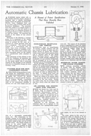
A PUMPING device which will, at
suitable intervals, expel a charge of lubricant into a chassis lubricating system, forms the subject of patent No. 572,513, from Tecalemit Ltd. and C. Le Clair, both of Great West Road, Brentfo rd, Middlesex. The patentees state that, whilst it is a simple matter to gear a pump to a very low speed, it is difficult to get it to function property if its plunger moves at only a fraction of an inch per minute. To overcome this trouble is the object of the scheme disclosed.
Referring to the drawing, a plunger pump (1) is connected to the chassis lubricators via the usual pipe lines. The pump is worked by the core of a solenoid (2), which descends when the coil is energized. The control switch consists of a worm-driven cam (3) which, once every revolution, closes the solenoid circuit by touching a contact (4). The initial drive comes from some convenient point on the vehicle, via a speedometer cable attached to worm 5.
The advantage of the scheme is that whilst the frequency of operation can he as slow as desired, it has no effect on the pump speed; this is governed entirely by the strength of the solenoid and gives an impulsive charge on every working woke.
CYLINDER HEAD FOR HIGHCOMPRESSION ENGINES A SOLUTION of the problem of mini
ti tbe compression space in small high-compression engines is shown in patent No. 572,371, by Morris Motors, Ltd., T. Brown and W. Thomas, all of Engines Branch, Courthouse Green, Coventry. In this design the bulk of the combustion chamber is located over the valve heads and con
sists of a rectangular round-ended cavity (1). The connection to the cylinder consists of an arched passage (2) formed mainly in the head, although a shallow notch is also cut out of the cylinder block. The design enables the valves to be given ample room for lifting—always a problem in small engines—whilst providing for a highcompression ratio.
A22 FOOD-STORAGE RECEPTACLE FOR VEHICLES TFHICLES such as long-distance V coaches, mobile canteens and the like, would be likely to make use of a device shown in patent No. 572,453, which comes from Trans-receivers Ltd., and L. Hermes, both of 444, Ewell Road, Surbiton, Surrey. The patent shows a cooled storage cupboard for foodstuffs; it is not actually refrigerated, but is arranged so as to make the maximum use of the passing air stream.
In the drawing, 1 is the floor of the vehicle and 2 the food cupboard. The latter is of double-walled construction, and the intervening space is filled with heat-resisting material such as kapok. Under the vehicle is a forward-pointing air scoop (3) with an efficient filter in the inlet. A similar scoop faces the rear, and it, too, is fitted with a filter.
When the vehicle is in motion, dean air is passed up into the cupboard and extracted by the rear scoop. Except in a dead calm, the air current would also flow slowly when the vehicle was at rest.
AIR CONTROL FOR ENGINES USING FUEL INJECTION
FROM the Rover Co., Ltd., and M. Wilks, both of Chesford Grange, Kenilworth, Warwickshire, comes, in parent No. 572,562, a scheme for correlating the supply of air and fuel in an engine employing injection instead of carburation. The scheme consists of a variable-ratio coupling between the Met pump and the air valve.
Referring to the drawing, the induction pipe (1) is opened to the atmosphere, via a spring-loaded poppet valve (2). The output of the injection pump is regulated by a lever (3), which is shown in its mid-position, the position of minimum output being to the extreme right. The pump control moves a rod (4) to which is attached the return spring of the poppet valve. When this rod is moved, the centre of spring pressure is moved also, along a lever (5). The effect is to give a stronger closing force when the pump output is at a minimum and vice versa.
BONDED-ON WATER JACKETS FOR ENGINE CYLINDERS THE ordinary monobloc cylinder casting, with its intricate water passages, is a complex and expensive item to cast, and it is surprising that, with modern methods, some more simple scheme has not been evolved. An improvement in this respect forms the subject of patent No. 572,463, . which comes from the Cierva Autogiro Co., Ltd., 12, South Place, London, E.C.2, and C. Pullin. Although the scheme is shown as applied to an air
craft 'engine, its use is not limited to this.
The water jacket in this case is a sheet-metal shell (1) shaped to fit the cylinder at the bottom and flanged at the top to receive the cylinder head. It is permanently attached at points 2 and 3 by a rubber-bonding process which forms not only a perfect seal, but also accommodates itself to slight differences in length" caused by thermal I expansion.