


An Engine Built of Sheet Metal
Page 64
If you've noticed an error in this article please click here to report it so we can fix it.
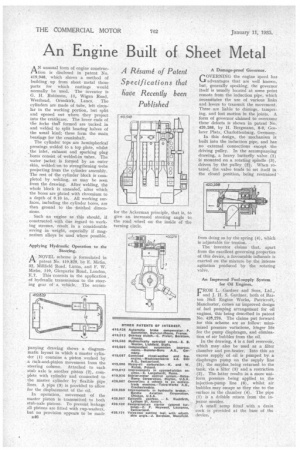
AN unusual form of engine construction is disclosed in patent No. 419,948, which shows a method of building . up from sheet metal those parts for which castings would normally be used. The inventor is G. H. Robinson, 11, Wigan Road, Westhead, Ormskirk, Lancs. The cylinders are made of tube, left circular in the working portion, but split and opened out where they project into the crankcase. The lower ends of the forks thuT formed are tucked in and welded to split bearing halves of the usual kind: these form the main bearings for the crankshaft.
The cylinder tops are hemispherical pressings welded to a top plate, whilst the inlet, exhaust and sparking plug bores consist of welded-in tubes. The water jacket is formed by an outer skin, welded -on-to strengthening webs projecting from the cylinder assembly. The rest of the cylinder block is completed by welding, as may be seen from the drawing. After welding, the whole block is annealed, after which the bores are plated with chromium to a depth of 0.10 in. All working surfaces, including the cylinder bores, are then ground to the -finished dimensions.
Such an engine as this should, if constructed with due regard to working stresses, result in a considerable saving in weight, especially if magnesium alloys be used where possible.
Applying Hydraulic Operation to the Steering.
ANOVEL scheme is formulated in patent No. .419,829, bY E. DrIirfin, 32, • Millfield Road, Luton, and F. W. Mirfin, 110, Glenparke Road, London, E.7. This consists in the application . of hydraulic transmission to the steering gear •of a vehicle. The accOm
panying drawing shows a diagrammatic layout in which a master cylinder (1) contains a piston worked by a rack-and-pinion movement from the steering column. Attached to each stub axle is another piston (2), complete with cylinder and connected to the master cylinder by flexible pipe lines. A pipe (3) is provided to allow for the displacement of the oil.
In operation, movement of the master piston is transmitted to both stub-axle pistons. To prevent leakage all pistons are fitted with cup-washers, but no provision appears to be made B48 • A Damage-proof Governor.
GOVERNING the engine speed has advantages that are well known, but, generally speaking, the governor itself is usually located at some point remote from the induction pipe, which necessitates the use of various links and levers to transmit the movement. These are liable to daniage, tampering, and lost motion in the joints. A form of governor claimed to overcome these defects is shown in patent No. 420,268, by H. Bergmann, 8-9, Coslarer Plats, Charlottenburg, Germany.
In this design, the mechanism is built into the induction pipe, and has no external connections except the driving pulley. In the accompanying drawing, a heavy butterfly valve (1) is mounted on a rotating spindle (3), driven by the pulley (2). When rotated, the valve tends td set itself in the closed position, being restrained
from doing so by the spring (4), which is adjustable for tension.
The inventor claims that, apart from the excellent governing properties of this device, a favourable influenCe is exerted on the mixture by the intense agitation produced by the rotating valve.
An Improved Fuel-supply System for Oil Engines.
FROM L. Gardner and Sons, Ltd., and J. H. S. Gardner, both of Barton Hall Engine Works, Patricroft, Manchester, comes an improved design of fuel pumping arrangement for oil engines, this being described in patent No. 420,276. The claims put forward for this scheme are as follow: minimized pressure variations, Ringer life for the pump diaphragm, and elimination of air bubbles from the oil.
In the• drawing, 4 is a fuel reservoir, which may also be used as a filter chamber and pre-heater. Into this an excess supply of oil is pumped by a diaphragm pump on the supply line (5), the surplus being returned to the tank, via a filter (3) and a restriction (2). The latter results in a more uniform pressure being applied to the injection-pump line (6), whilst air bubbles may escape as they rise to the surface in the chamber (4). The pipe (1) is a dribble return from the injector nozzles. A small sump fitted with a drain cock is provided at the base of the device.