


Patents Completed.
Page 20
If you've noticed an error in this article please click here to report it so we can fix it.
Complete specifications of the following patents will be sent to any address in the United Kingdom upon receipt of eightpence per copy at the Sale Branch, Patent Office, Holborn, W.C.
A Novel Valve Combination.
Henri Pieper.—No. 20,053, dated 29th August, 1910.—This invention relates to internal-combustion engines, particularly to those working on a four-stroke cycle and consists in the combined use of two valves which, in the example illustrated, comprise a piston valve and a flat slide valve. The engine cylinder on the left-hand side communicates by a passage with ports controlled by the piston valve. These ports in their turn communicate with the inlet and exhaust passages, being open to either one as required be the flat slide valve. Alternative constructions are described in whirls two concentric piston valves or two flat slide valves are used. Both valves are operated from the half-speed shaft; the main valve opens its ports frcm the beginning of the exhaust stroke to the end of the admission stroke, and the auxiliary valve connects the passage with the exhaust and admission at the proper time.
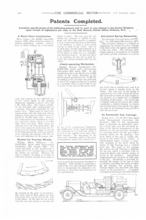
Strakes for Traction Wheels, William Albert McKinney. No. 14,519/1911, dated under Intinmational Convention, 15th August, 1910. The wheel described in this specification is comprised of two annular rims to which the spokes are secured. Between the rims a number of plates is riveted or otherwise suitably secured at an angle to
the tangent at the point of attachment. The outer ends of these plates are bent downward and extond beyond the rimsoi the wheel. At the edge the toe is bent over the rim and assists in securing the plates in place. The toes grip the soil before any pressure is applied to the plate, but when the pressure is applied, it is in a backward direction so that there is no tendency to form a wave which travels in front of the wheel. The toe of each plate extends approximately to point radially in line with the back edge of the plate in front but is a considerable distance from it. In this way there is no tendency for the soil to pack between the various elements and clog the wheel.
Clutch-operating Mechanism.
Daimler itletoren G-esellschaft.—No. 28,879/1910, dated under International Convention 26th April, 1910. In this specification there are details of a modification of the clutch described in the British patent specification No. 11,337/10. According to this invention the push bolt or rod of the toggle mechauism is guided by a member which is immovable in the direction of the axis of the power shalt.
ILL one of Jr-, esmstructiuns illustrated, the middle joint of the toggle mechanism has cum-meted to it a long link which is secured to the gearbox or to some other fixed member. The movement of the push rod is therefore radial to this point of attachment, and as the vertical meve
moot is small the horizontal movement is negligible. This ensures an equal movement of the two cones through which the drive is transmitted. An alternative construction is described and illustrated in this specificat ion,
Articulated Spring Suspension..
The Wolseley Tool and Motor Car—Cci., Ltd.—No. 633, dated 10th January, 1911. —This invention relates to a method of supporting the bodies of motor vehicles from their axles and applies particularly to the rear axles. The ordinary semielliptic spring is arranged at its forward end with a pivotal connection to a swivel
pin which has a vertical axis, and it is carried within a bracket fixed on the frame. The rear end of the spring is connected by two links, which are pivotally mounted to rotate at right angles to one another, to a dumb-iron or suitable extension of the frame. The swivel pin is formed with a lower jawed end, which constitutes a hollow housing to receive the forward end of the spring, the opposite ends of the housing being pierced to take the pivot pin.
An Automobile Gun Carriage.
Krupp, A.G.—No. 21,770 of 1911, dated under International Convention 6th December, 1910.—In this specification there is described an automobile carrying a pivot gun, and the invention relates to the special arrangement of the platform for the gun and the connection of a securing device for the gun with a securing device for the platform. The pivot stand of the gun is rigidly connetted to the frame of the vehicle. A forked-shaped upper carriage is rotatably mounted in the pivot stand by means of ball hearings and a vertical pivot pin. The frame of the carriage also carries on ball bearings a platform for the gun which is provided with an armoured shield with suitable means of access to the platform. Ammunition compartments are situated on both sides of the gun. Mechanism is provided for securing the muzzle of the gun so that in ordinary travelling the strain is taken off the training and pointing gear. Various details are described and illustrated in the specification. A generalarrangement drawing is reproduced below.