


Steering, 6
Page 52
If you've noticed an error in this article please click here to report it so we can fix it.
THE WORM and sector steering gear, illustrated in Figure 1, is a development of the worm and wheel used on earlier designs. A case-hardened steel worm is fastened to the lower end of the steering column and is supported by ball races. The sector is located at one end of the cross-shaft while the drop arm is fastened on tapered splines at the other. The crossshaft is carried in phosphor bronze bushes.
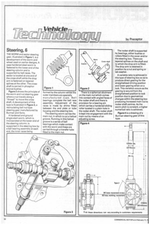
Figure 2 shows the principle of the worm and nut steering gear where a nut travels along a "thread" to move the cross shaft. A development of this type is illustrated in Figure 3, a recirculating ball nut type steering gear manufactured by Burman and Sons.
A hardened and ground single-start worm, which is incorporated at the lower end of the steering column, is supported in the steering box by a ball bearing assembly at each end, the inner races being formed by the column whilst the outer members are specially manufactured cups. Ball bearings complete the ball race assembly. Adjustment of the races is made by shims fitted between the end plate or tube housing and the steering box.
The steering worm carries the main nut, in which is cut a helical groove. Running in this helical groove is a series of ball bearings which make contact with the worm and these are carried through a transfer tube fitted to the main nut. There is a spherical abutment on the main nut which comes into contact with angled faces of the rocker shaft and there is provision for a bearing pin which carries a hardened sliding roller located in a plain hole in the rocker shaft. The rocker shaft is kept into engagement with the main nut by means of an adjusting screw. The rocker shaft is supported by bearings, either bushes or rollers fitted in the cover and/or the steering box. There are tapered splines on the shaft end to which the drop arm is fitted. The drop arm is retained in position by a nut and spring or tab washer.
A variable ratio is achieved in this type of steering box so as to produce direct gearing for the straightahead driving position and lower gearing when on a lock. This variation occurs as the gearing is wound from the straightahead position to lock position due to geometrical changes within the steering box producing increased main nut to rocker shaft centres. As the worm pitch is constant, a higher numerical ratio is achieved.
Figure 4 is a drawing of a Burman steering gear of this type.